EN
EN

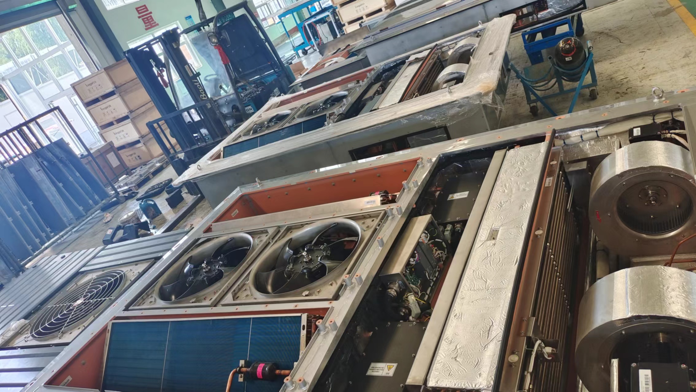
Last fall, a commercial AHU manufacturer with over a decade of experience reached out: "Dannis, our AHU hits the airflow target perfectly during factory testing. But after a month on site, airflow drops 20%. We've tried three fan suppliers—same AC axial fan specs—and they all do the same thing. Is it the fans, or is it us?"
He sent over the AHU configuration: mixing section + G4 pre-filter + F7 bag filter + cooling coil + heating coil + humidifier + fan section—a textbook commercial office AHU, design airflow 3,000 m³/h, using a 350mm AC induction motor axial fan running at fixed speed with no speed control.
At factory test, every section was brand new: pre-filter pressure drop 50 Pa, cooling coil dry-operation 80 Pa, humidifier off. Total system resistance: ~180 Pa. Fan was operating comfortably in its rated zone. Airflow: 3,000 m³/h. Passed.
One month later, on site: pre-filter loaded to 120 Pa, cooling coil running wet (actual cooling mode) at 150 Pa, humidifier active at 30 Pa. Total system resistance: 350 Pa—nearly double the factory test value. And the AC fan? No speed control. Operating point slid left along the PQ curve. Airflow dropped from 3,000 m³/h to 2,400 m³/h.
First take: The fans weren't faulty. All three suppliers were fine. The fundamental flaw was in the selection logic—the fan was sized for factory-new conditions only, with no provision for in-field variable resistance.
The root cause becomes clear when you plot system resistance over time:
| Timeline | Condition | Filter | Coil | Humidifier | Total Resistance | Airflow |
|---|---|---|---|---|---|---|
| Factory test | New·Dry coil | 50 Pa | 80 Pa | 0 Pa | ~180 Pa | 3,000 m³/h ✅ |
| 1 month in | Filter loading·Wet coil | 120 Pa | 150 Pa | 30 Pa | ~350 Pa | 2,400 m³/h ❌ |
| 6 months in | Filter end-of-life·Wet coil | 200 Pa | 150 Pa | 30 Pa | ~430 Pa | 1,800 m³/h ❌ |
An AHU is not a static system. Filters load, cooling coils switch from dry to wet operation, humidifiers cycle on and off—every one of these changes alters the resistance the fan sees. A fixed-speed AC fan has exactly one degree of freedom on its PQ curve: resistance rises → operating point shifts left → airflow drops. Without speed control, it can only follow the curve downhill.
The fix didn't require a larger fan, a VFD, or a redesigned AHU cabinet. It required one thing: a motor that can adjust its speed in response to changing resistance—an EC motor.
We recommended the FG3G350-2APL-90—same diameter (350mm), same voltage (230VAC), same airflow class (3,500 m³/h), but with the AC induction motor replaced by a BLEC92 external rotor EC brushless motor with native 0-10V/PWM variable-speed control.
| Design Element | Selected | Why It Mattered Here |
|---|---|---|
| Fan type | Axial (G-type·guarded) | High flow·axial discharge·matches AHU airflow direction |
| Motor type | EC brushless (BLEC92) | Native 0-10V/PWM speed control·stepless·no VFD needed |
| Voltage | 230VAC | Direct mains connection·no external DC supply required |
| Impeller diameter | 350mm | Same dimensions as original—zero AHU cabinet modifications |
| Parameter | Value | Note |
|---|---|---|
| Model | FG3G350-2APL-90 | PL electrical·90 mechanical series |
| Fan category | Axial fan (with guard grille) | G-type |
| Impeller diameter | 350 mm | — |
| Rated voltage | 230 VAC | 50/60Hz |
| Rated speed | 1,580 RPM | 0-10V/PWM stepless speed control |
| Max airflow | 3,500 m³/h | Free-air condition |
| Max static pressure | 135 Pa | Zero-flow condition |
| Rated power | 160 W | Full load |
| Rated current | 1.15 A | At 230VAC |
| Sound pressure level | 63 dB(A) | Rated condition·1m |
| Motor type | BLEC92 | 3-phase EC brushless·external rotor |
| Speed control | 0-10VDC / PWM | Standard |
| Protection rating | IP44 | Indoor AHU installation |
| Operating temperature | -25 ~ +60 ℃ | — |
The client asked the obvious question: "Same impeller size, EC costs more than AC. Is it worth it?"
We gave him a comparison table and three decision criteria:
| Metric | Original: AC Induction Motor | New: EC Brushless (BLEC92) | Difference |
|---|---|---|---|
| Full-load efficiency | ~55-65% | >85% | 30-40% energy saving |
| Speed control range | Fixed / requires VFD | 0-100% stepless·native | VFD cost eliminated |
| Starting current | 5-7× rated | <1.2× rated | Minimal grid impact |
| Power factor | 0.6-0.75 | >0.95 | Low reactive losses |
| Noise | 68-72 dB(A) | 63 dB(A) | 5-9 dB quieter |
| Service life | 20,000-30,000h | 40,000-60,000h | 2× lifespan |
Three dimensions that decided this case:
① Speed control is mandatory, not optional: This AHU's multi-stage dynamic resistance meant the fan had to have speed control. The total cost of AC motor + VFD + control cabinet + wiring + commissioning actually exceeded the all-in-one EC solution.
② Noise-sensitive location: The AHU room was directly adjacent to office space. 72 dB(A) AC → 63 dB(A) EC. That 9 dB difference meant one less stage of sound attenuation—and the savings on the silencer roughly covered the EC price premium.
③ VAV-ready for future projects: The client had upcoming projects requiring variable air volume. With AC+VFD architecture, upgrading to VAV means reworking the control logic. With EC, the 0-10V/PWM interface connects directly to the DDC—switching from CAV to VAV requires zero changes to the fan section.
Every selection must survive the PQ curve. Here's the FG3G350-2APL-90 at 1,580 RPM, overlaid with this case's actual system resistance profile:
| Operating Point | Airflow (m³/h) | Static Pressure (Pa) | Corresponding Case Condition |
|---|---|---|---|
| Free air | 3,500 | 0 | — (theoretical maximum) |
| Rated point ⭐ | ~1,750 | ~70 | Factory-new·dry coil → speed can be reduced |
| 1 month in | ~3,000 | ~90 | EC ramps to ~85% speed·airflow pulled back to design |
| 6 months in | ~3,000 | ~110 | EC ramps to ~95% speed·still within rated zone |
| Shutoff | 0 | 135 | Maximum static pressure·zero flow |
Conclusion: The FG3G350-2APL-90, with 135 Pa maximum static pressure, keeps the operating point within its rated zone even as system resistance reaches 2.4× the original design value. Where the AC fan had already dropped to 2,400 m³/h, the EC fan—with closed-loop speed control—pulls airflow back to 3,000 m³/h while staying comfortably below 90% of maximum speed.
The client retrofitted one prototype AHU with the FG3G350-2APL-90, paired with a 0-10V static pressure sensor for closed-loop control. After a full 6-month filter cycle, here's what they reported:
Zero decay over full filter cycle. EC closed-loop control automatically compensated for filter loading and wet coil conditions.
160W vs. ~250W original. 12 h/day operation. 400-500 kWh annual saving per unit.
63 vs. 72 dB(A). AHU room adjacent to offices. Noise complaints stopped.
Original AC required quarterly belt tensioning. EC direct-drive: zero maintenance.
| Metric | Before (AC Fixed-Speed) | After (EC Variable-Speed) |
|---|---|---|
| Factory airflow | 3,000 m³/h | 3,000 m³/h (speed reduced to match) |
| Airflow after 6 months | 1,800 m³/h (-40%) | 3,000 m³/h (closed-loop compensation·zero decay) |
| Input power (operating) | ~250 W | ~160 W |
| Noise @1m | 72 dB(A) | 63 dB(A) |
| Speed control | None | 0-10VDC direct to DDC |
| Maintenance interval | Quarterly (belt tension) | Maintenance-free (direct drive·no belts) |
The client has since specified the FG3G350-2APL-90 in three follow-up projects and is evaluating its larger-airflow variants for another product line.
This project taught us several things worth sharing:
If you're working on a similar AHU project, here's the full FG3G350 platform matrix:
| Model | Motor | Voltage | Max Airflow | Max Pressure | Power | Noise | Best For |
|---|---|---|---|---|---|---|---|
FG3G350-2APL-90 |
EC | 230VAC | 3,500 m³/h | 135 Pa | 160W | 63dB | AHU standard·EC speed control·this case |
FG3G350-2AGL-90 |
AC | 230VAC | 3,500 m³/h | 135 Pa | — | — | AHU CAV·budget-sensitive |
FG3G350-2APN-90 |
EC | 230VAC | 3,500 m³/h | 135 Pa | 160W | 63dB | PN electrical·drop-in alternative |
FG3G350-48PL-90 |
EC | 48VDC | 3,500 m³/h | 135 Pa | 160W | 63dB | DC-powered·special applications |
Selection note: PL and PN have different speed-control signal polarities. Wire them backwards and the fan runs at minimum speed regardless of the control signal. Confirm your DDC output type before ordering.
Dealing with AHU airflow decay? Need the full PQ curve data for FG3G350-2APL-90 to validate against your system? Contact our application engineering team: [email protected]. Send us your AHU section configuration and resistance estimates—we'll run the PQ matching for you.