A European ventilation system integrator with over 15 years of industrial air handling experience took on a retrofit project for a food additive plant in Eastern Europe. The existing system also used a 630mm axial fan — airflow and static pressure were adequate on paper. But after less than a year of operation, the fan was failing repeatedly. A teardown inspection revealed two root causes:
The client's three critical requirements:
The previous fan was also a 630mm axial — airflow and static pressure were adequate on the datasheet. Yet it failed repeatedly within a year. The teardown told the real story:
The old bracket's adjustment joints used nylon PA6 plastic heads, clamped by a bolt to lock the angle. The design intent was light weight and low cost, but under continuous duct vibration (measured 2.8–4.5 mm/s), the plastic friction surfaces experienced progressive wear. Clamping force degraded by approximately 30% per quarter. Within six months, the joint gap exceeded 0.5mm, shifting the fan off its mounting axis. The impeller began scraping the duct wall — producing harsh noise and damaging blades.
Root cause: Plastics creep and wear under sustained micro-vibration. This is an inherent material property — no amount of "tightening it more" can fix it. The adjustment mechanism must be all-metal.
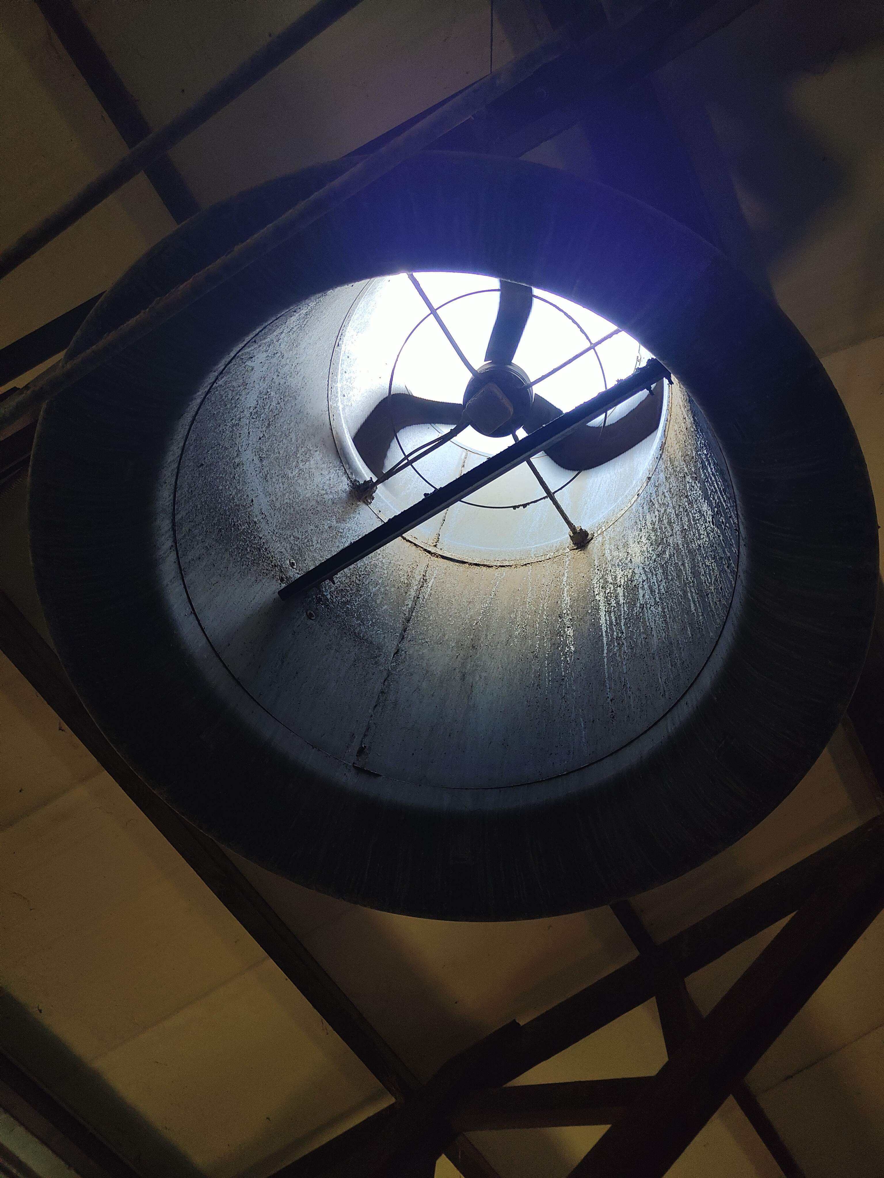
In a duct wall exhaust installation, the bracket lives in a cycle of condensation and chlorine-based cleaning solutions (sodium hypochlorite is standard for food plant sanitation). The old bracket used galvanized steel. The zinc layer dissolved rapidly in the presence of chlorinated cleaners. Within six months, widespread red rust appeared:
Conclusion: The fan itself was never the problem — same diameter, same airflow. The failures were 100% in the bracket material and joint design. All-304-SS construction with metal-on-metal locking joints is the only viable solution.
| Parameter | Value | Notes |
|---|---|---|
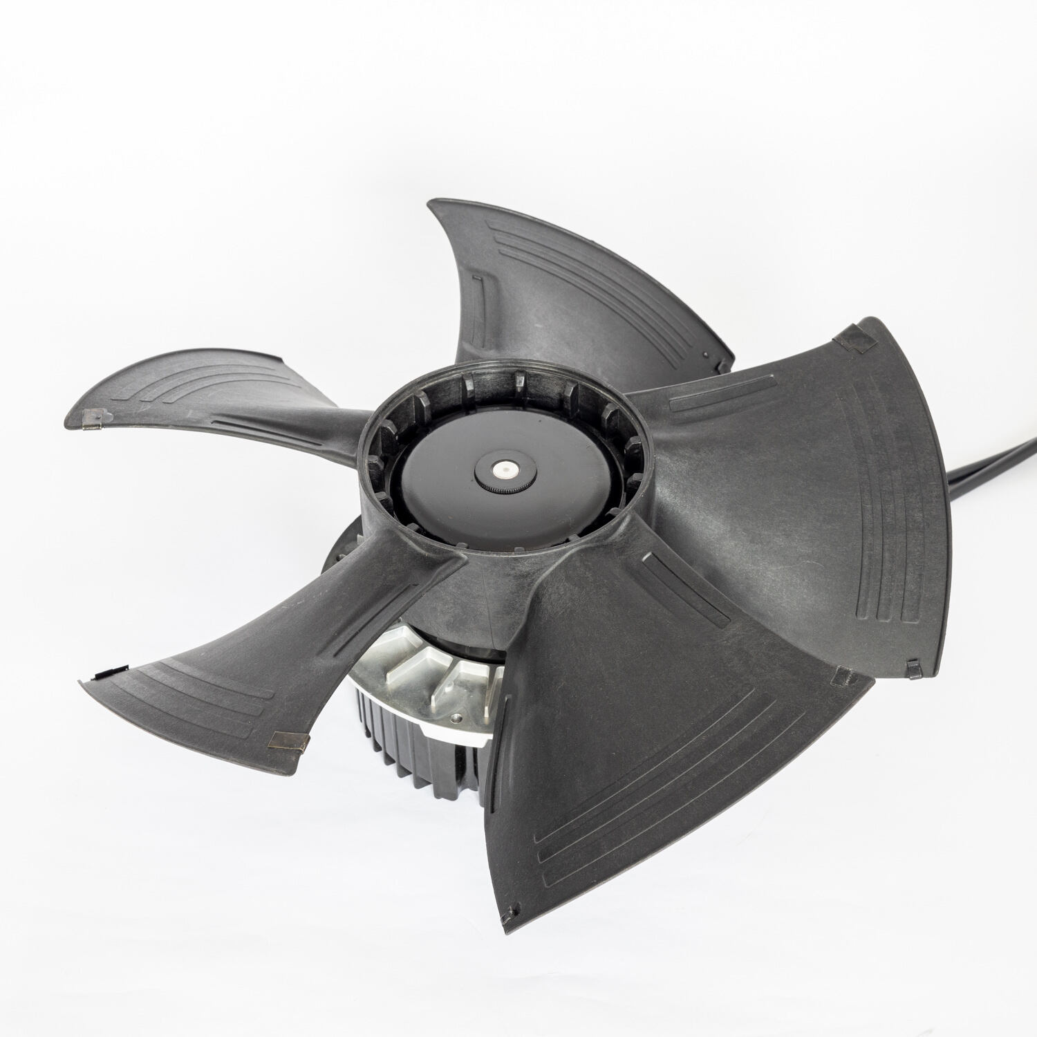
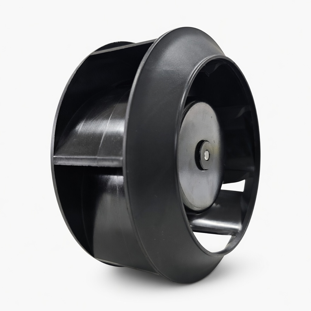
| Model | FG3G630-4AGL-3A | Large-diameter EC tube axial with guard |
| Impeller | 630 mm | Axial impeller |
| Motor | EC brushless DC | Nominal ~1150 rpm · efficiency ≥ 90% |
| Rated Power | 0.8 kW | EC high-efficiency · low power draw |
| Max. Airflow | 14,500 m³/h | Free air, zero back pressure |
| Max. Static Pressure | 240 Pa | Zero-flow shutoff pressure |
| Sound Level | 69 dB(A) | Full speed |
| Standard IP Rating | IP44 | Dust-protected + Powerful water jets |
| Custom IP Rating | IP65 | Fully dust-tight + Water jets · potted terminal box |
| Speed Control | 0–10V / PWM / Modbus RTU | 0–10V selected · plant DCS integration |
| Certifications | CE / ISO 9001 / ErP 2026 | — |
| Weight | ~15 kg | Including motor + housing + guard |
EC fans differ fundamentally from traditional AC fans — they have no separate motor junction box. The EC control board (rectifier + VFD drive + 0–10V/PWM signal interface) is integrated and enclosed within the motor's terminal cover. The FG3G Series ships standard at IP56 — suitable for most outdoor duct installations. For this project, the upgrade to IP65 was achieved through control board potting and targeted sealing improvements:
Potting is the standard process for achieving IP65 on EC fans — it adds no external dimensions, no additional enclosures, and approximately 8–12% to unit cost. For a continuous-production exhaust line, this premium eliminates the risk of a water-damaged control board entirely.
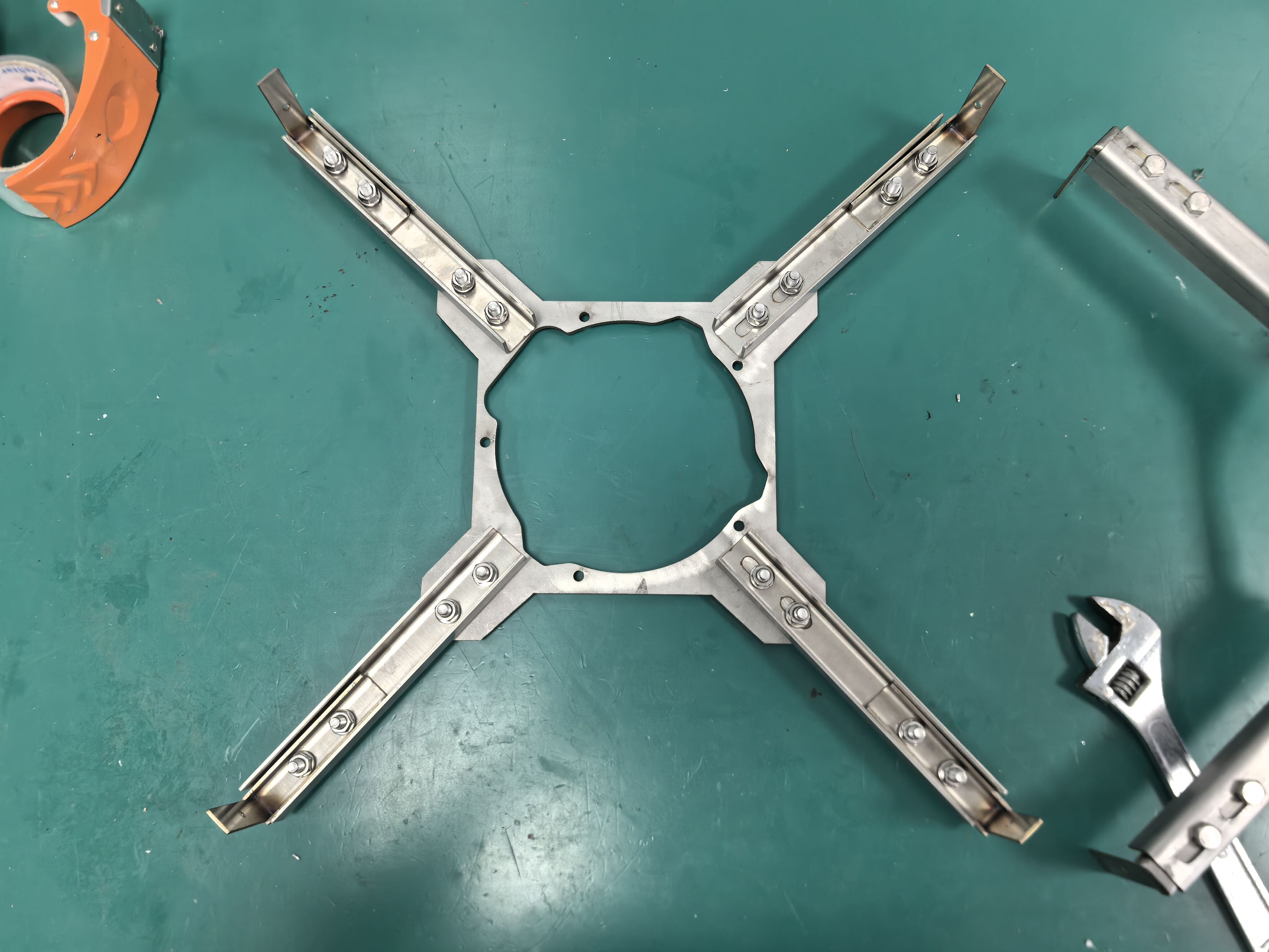
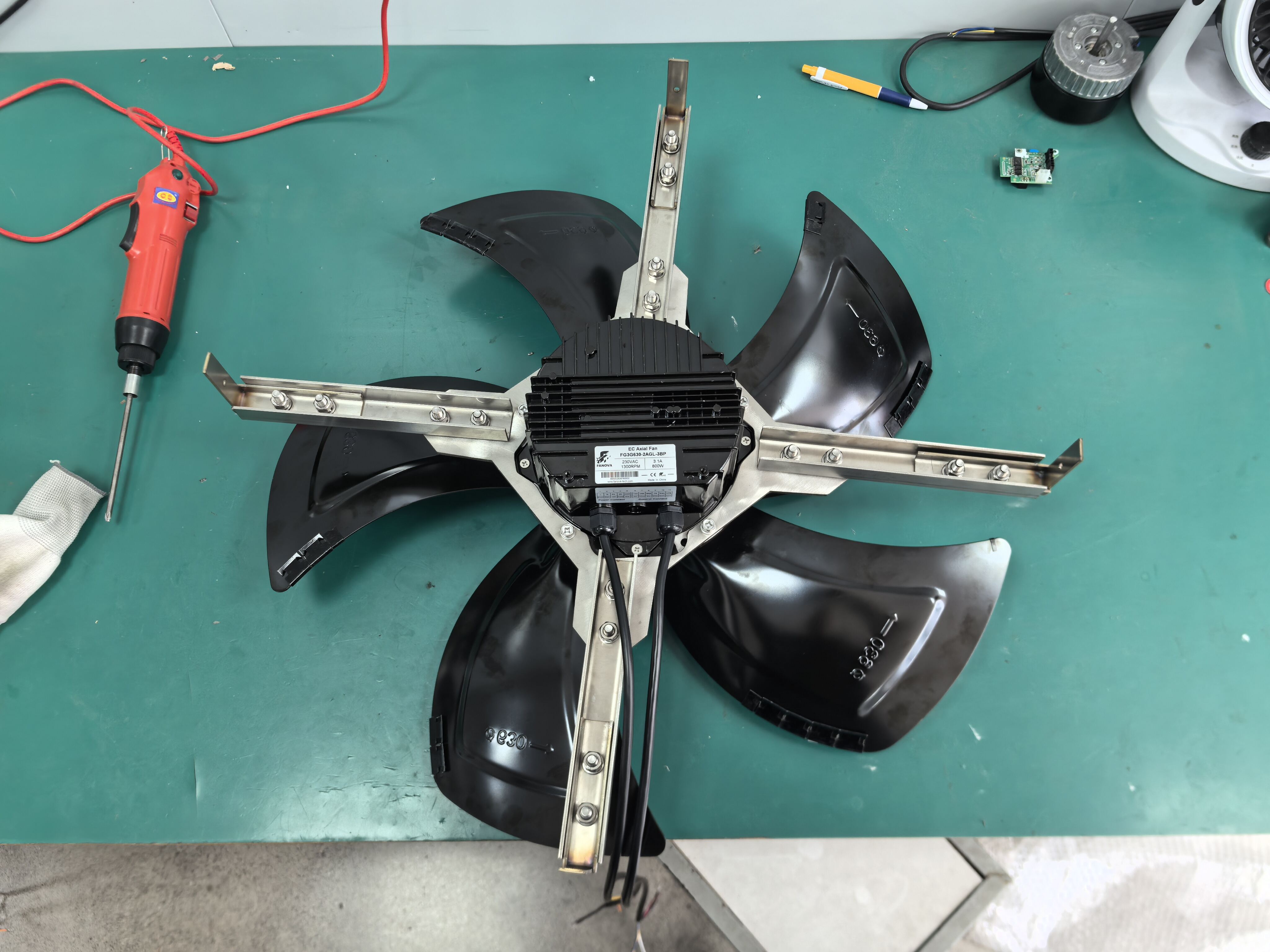
Addressing both failure modes of the old bracket — plastic joint loosening and galvanized steel rust — the replacement bracket was redesigned with every component in 304 stainless steel, every adjustment joint metal-on-metal.
| Operating Mode | Airflow Demand | 0–10V Signal | Speed | Power Draw |
|---|---|---|---|---|
| Standby ventilation | 2,000 m³/h | 2.0V | ~400 rpm | 0.15 kW |
| Normal production | 6,000 m³/h | 5.5V | ~800 rpm | 0.4 kW |
| Peak exhaust | 10,000 m³/h | 9.0V | ~1,100 rpm | 0.7 kW |
The EC motor's part-load efficiency is the standout advantage. Standby power draw is ~0.15 kW — over 60% lower than an equivalent AC motor — saving over 3,000 kWh/year.
Three field essentials: ① Verify G½" drain plug faces downward — schedule periodic condensate draining. ② Maintain ≥ 400mm clearance on inlet side for impeller access. ③ Verify earth continuity: SS duct → flange → bracket → fan housing ≤ 0.1Ω.
| Parameter | Design Target | Measured | Deviation |
|---|---|---|---|
| Airflow at 200 Pa back pressure | 8,500 m³/h | 8,380 m³/h | −1.4% |
| Max. Static Pressure | 240 Pa | 235 Pa | −2.1% |
| Sound Level at 3m (full speed) | ≤ 69 dB(A) | 67.5 dB(A) | ✅ Better than rated |
| Motor Efficiency | ≥ 90% | 91.3% | ✅ |
| Vibration Velocity | ≤ 3.5 mm/s | 2.8 mm/s | ✅ |
| IP65 Seal Integrity | No water ingress | No water ingress | ✅ Passed pressure-wash test |
The old fan was also 630mm — the fan itself was never the problem. Duct wall exhaust installations subject the mounting system to a triple threat: condensation, chlorine-based cleaners, and continuous vibration. Plastic joints will loosen. Galvanized steel will rust. When selecting a fan for this application, impeller diameter and airflow are just the starting point — bracket material and joint design determine system lifetime. All-304-SS construction + all-metal locking joints + EPDM isolation pads: all three are non-negotiable.
| Installation Location | Standard IP | Recommendation |
|---|---|---|
| Indoor, dry duct | IP44 | Basic dust protection |
| Indoor, condensing duct | IP54 | Splash-proof |
| Outdoor, with weather hood | IP55 | Low-pressure water jets |
| Duct wall embedded · direct outdoor exposure | IP56 standard · IP65 custom | Powerful water jets + fully dust-tight |
| Fully exposed, no weather protection | IP66 | Heavy seas / powerful water jets |
The FG3G Series' standard IP56 rating already covers most duct-wall-embedded scenarios. This project's IP65 upgrade was driven by daily pressure-washing. The ~8–12% cost premium is easily justified against the downtime cost of a water-damaged motor on a continuous-production exhaust line.
304 SS duct + non-SS brackets = galvanic corrosion within 6–12 months in condensing environments (electrode potential difference > 0.3V). Specify uniform 304 SS for all fasteners, brackets, and flange plates.