EN

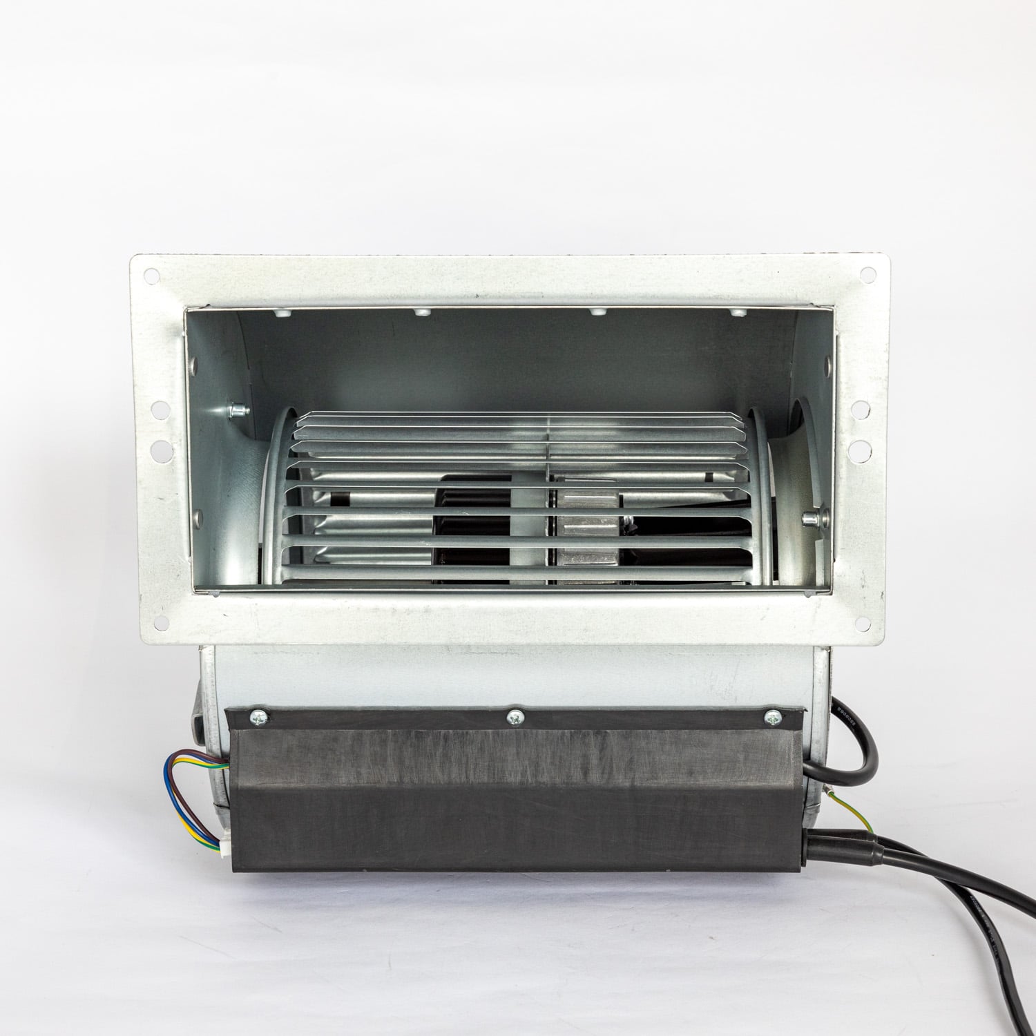
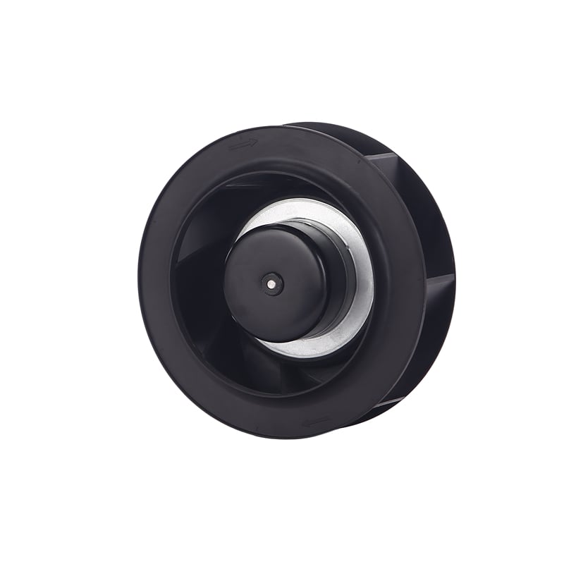
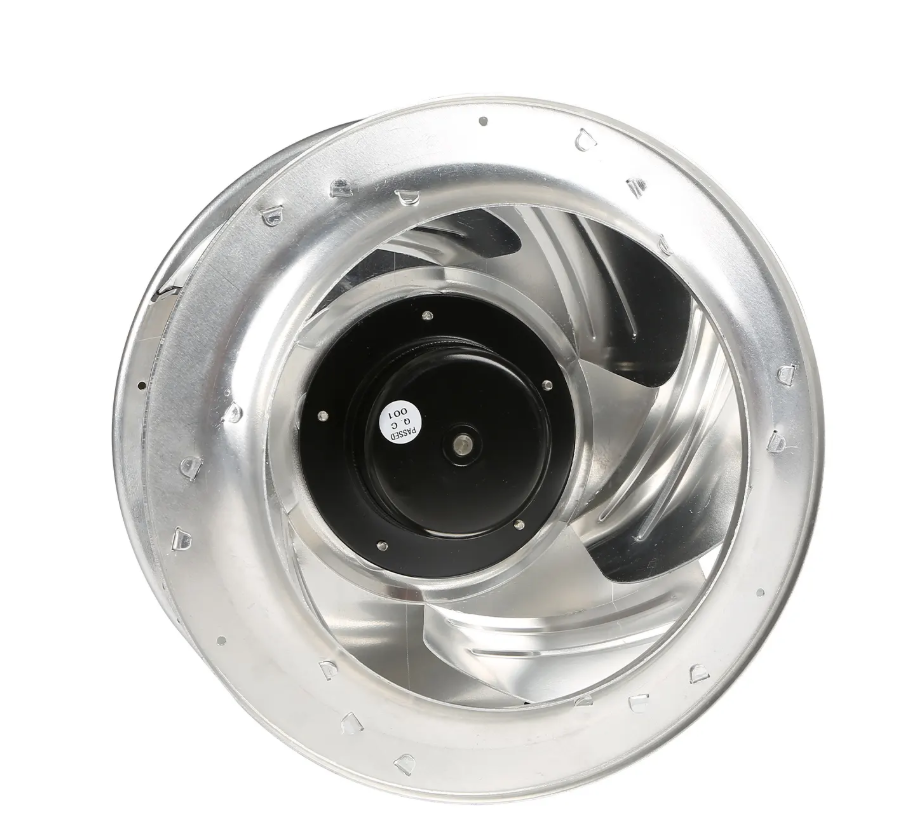
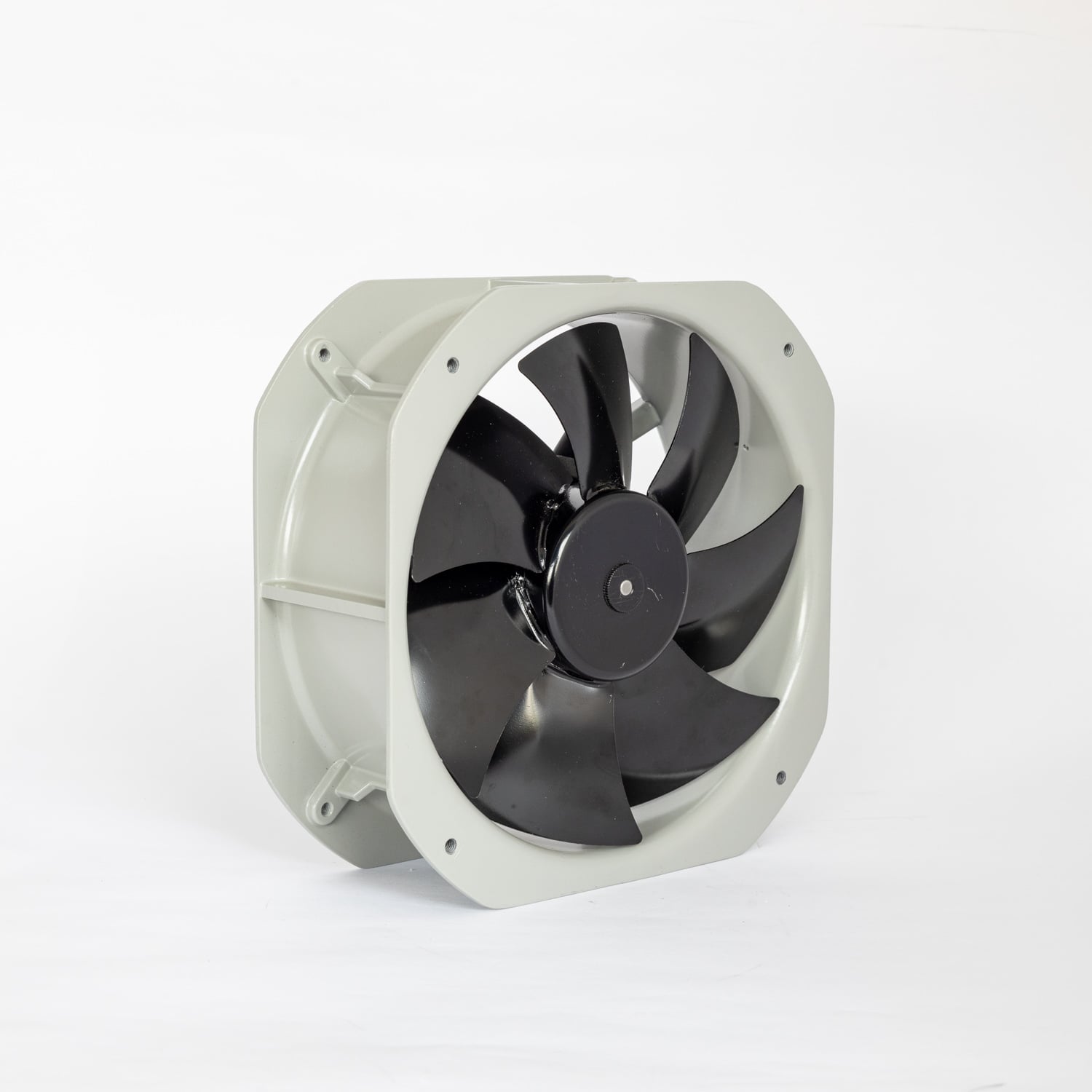
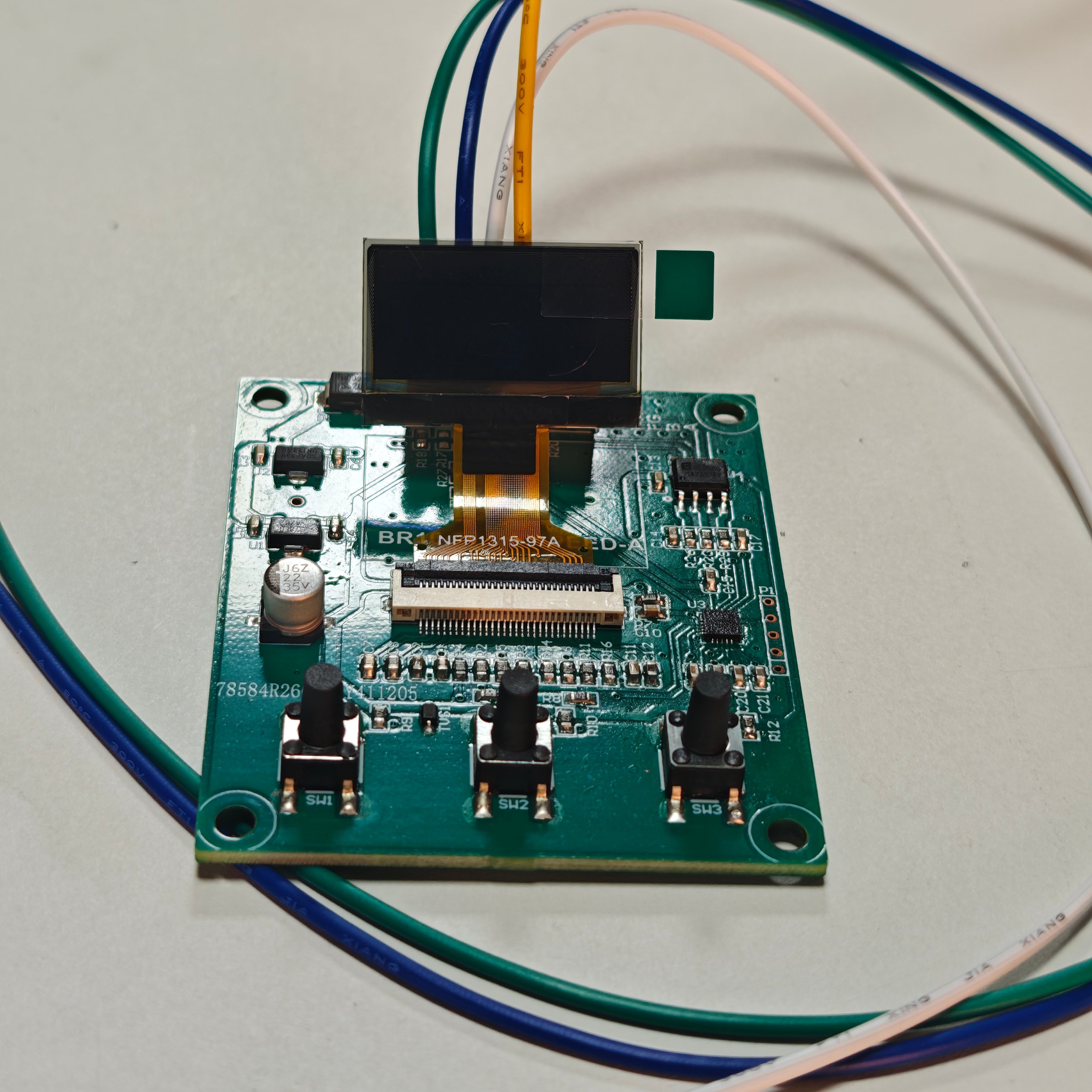
Every EC fan we ship already has a speed controller inside it. The new external EC fan speed controller exists because that inner controller is built to be commanded, not to be operated. It puts the command interface where a technician can reach it: three buttons, a display that reads setpoint and actual rpm, and three ways in — 0-10V, PWM and Modbus RS485.
Fanova (Suzhou) Motor developed the module for OEMs and system integrators who build EC fans into air handling units, cold rooms, cleanrooms, battery enclosures and test benches, and who need the same control behavior across a mixed fleet.
At a glance
An EC fan's integrated electronics expose a low-voltage interface: a 0-10V or PWM command input, a tachometer output, and on some models an RS485 port. That is enough for a BMS that already speaks the same language. It is not enough for the panel builder who has to do four things at handover.
Each is a small problem on its own. Together they are the reason external controllers exist — and the reason a fan with perfectly good internal electronics still arrives at a panel with nowhere to plug in a display.
0-10V, PWM and Modbus RS485 are usually listed as features. In a panel they are three answers to three different questions, and the host system normally decides which one is used.
| Input | Signal | Typical host | Watch for |
|---|---|---|---|
| 0-10VDC | Voltage maps to 0–100% speed | BMS analog output, potentiometer, thermostat loop | Ground offset, cable length, and the dead band below about 1 V where most fans stop |
| PWM | Duty cycle maps to speed | PLC, embedded board, opto-isolated output | Logic polarity (0% duty means stop on some fans, full speed on others) and the carrier frequency range |
| Modbus RS485 | RTU frames, read and write | PLC, SCADA, multi-fan network | A/B polarity, termination, address plan and a common reference |
The 0-10V input is the lingua franca of building management. A potentiometer, a thermostat loop or an analog output card can all drive it, and the fan does not care which. The practical limits are ground offset and cable length: a 0-10V signal referenced to a different ground reads a few percent high or low, and the fan follows that error without complaint.
PWM is what a PLC or an embedded board produces natively — no DAC, no reference voltage, and it survives an opto-isolated output. What it does not survive is a brand mismatch. EC fan makers do not agree on whether 0% duty means stop or full speed, and every fan has a carrier frequency window it will accept.
Modbus is the only one of the three that reads back. Setpoint goes out, actual speed and status come in, over one twisted pair. On a bus with ten fans, the address plan, the termination resistors and the A/B polarity decide whether it works — not the protocol.
Panel displays are sold as convenience. In practice they cut commissioning time, because they put the command and the feedback side by side.
Three buttons cover source selection, minimum and maximum speed, pulse scaling and the Modbus address. No software, no dongle. A technician with the wiring diagram can bring a fan into service and leave the setpoints written on the panel schedule.
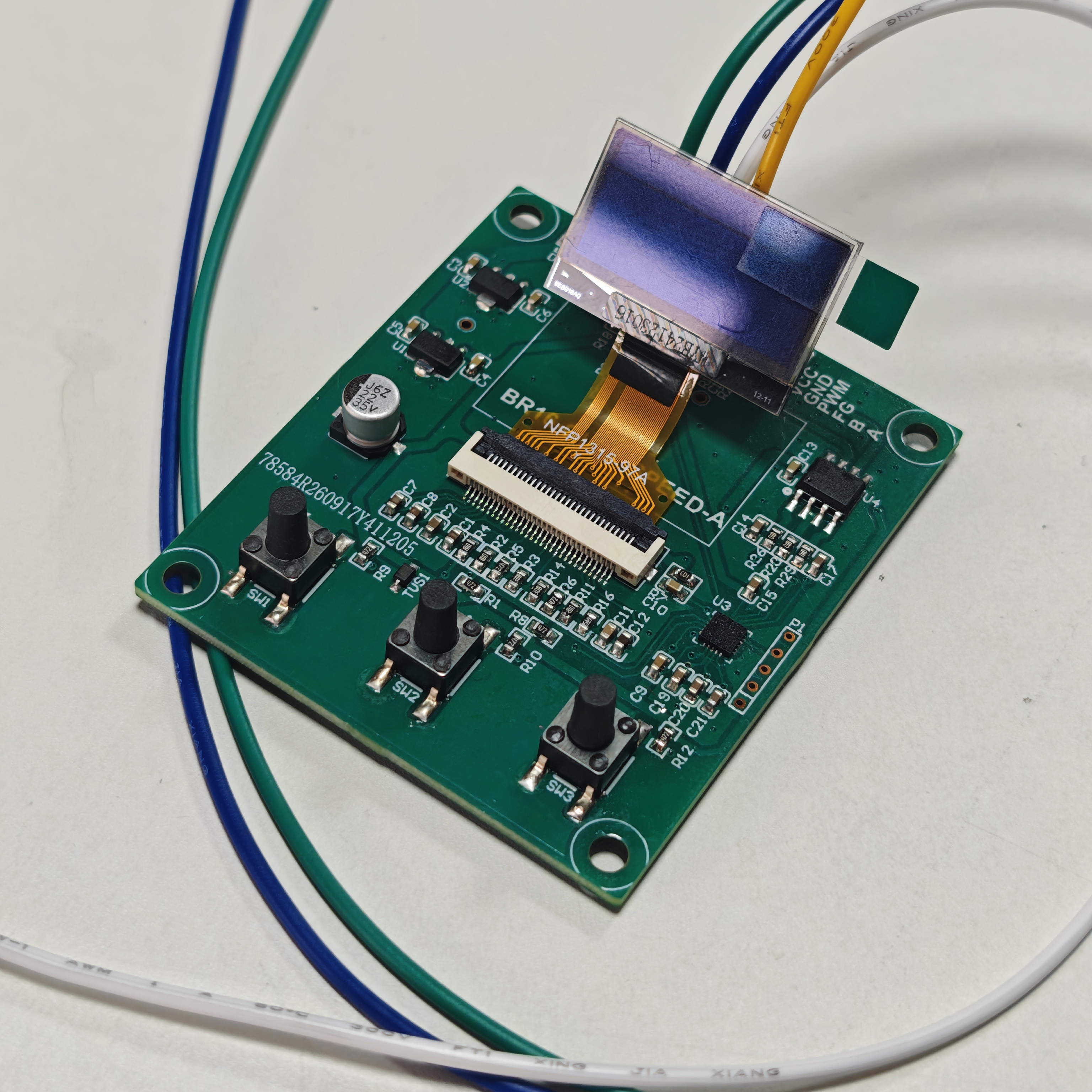
A tachometer output is a square wave. The controller counts edges and converts to rpm:
rpm = 60 × fFG ÷ N
where fFG is the tach frequency in hertz and N is the number of pulses the fan produces per revolution. Fan makers do not standardize N. Three pulses per revolution is common on EC centrifugal fans; axial models vary; a replacement from another supplier may differ again. Set N wrong and the display is wrong by exactly that ratio.
| Pulses per revolution (N) | Tach frequency at 1,200 rpm | Displayed rpm, N set correctly |
|---|---|---|
| 1 | 20 Hz | 1,200 |
| 2 | 40 Hz | 1,200 |
| 3 | 60 Hz | 1,200 |
| 4 | 80 Hz | 1,200 |
Leave N at 2 on a 3-pulse fan and a true 1,200 rpm reads 1,800. A fixed-scaling tachometer therefore forces a different part number for every fan. This module accepts 1 to 16 pulses per revolution, so one stocked controller covers a mixed fleet, and replacing a fan does not mean replacing the display.
The EC fan speed controller suits installations where the fan is one component of a larger panel and somebody has to operate it.
It is the wrong choice for a single fan running at one speed with no display requirement. The fan's own 0-10V input is cheaper, needs two wires and adds nothing that can fail. The external module earns its cost when at least two of these are true: more than one fan brand on site, a Modbus handover, a display at the panel, or a service team that swaps fans without a laptop.
Step six is the one that gets skipped. A display that agrees with a hand tachometer at three points is a calibrated instrument; one that has never been checked is a decoration.
Send these six items and we will return a unit with the pulse setting already matched to the fan:
Sample units of the external EC fan speed controller, the Modbus register map and the terminal assignment are available on request from FANOVA application engineering. Send the fan model and the host interface; we will return a configured controller and the wiring schedule for the panel.
Specifying an EC fan with a panel-mounted control point?
Send FANOVA application engineering your fan model, host signal and panel layout. We return a wiring schedule with the pulse setting and Modbus address already assigned.
No. A VFD creates a variable-frequency three-phase output for an induction motor. This module commands the electronics already built into an EC fan, over the fan's 0-10V, PWM or RS485 input. It never sees the motor current.
If the fan accepts a 0-10V or PWM command and provides a tachometer output, it can normally be driven — provided the PWM logic matches and the pulse count falls inside 1 to 16. Check the fan's command polarity and carrier range before ordering.
The nameplate figure is nominal at rated voltage and full command. Actual speed depends on load and setpoint. If the difference is a clean ratio — 1.5 times, twice — the pulse setting is wrong rather than the fan.
Whatever the host already has. Use 0-10V for a BMS, PWM for a PLC or embedded board, and Modbus when you need readback, fault status or more than a few fans on one cable.
A Modbus RTU segment supports 32 unit loads without a repeater, but the practical limit is usually the master's scan time and the cable run. Above eight to ten fans, plan the addresses and the termination before the cable is pulled.
Ask before specifying. The 1 to 16 range covers the EC fans we commonly supply; a fan outside that range needs a divider or a different tach source.
Related reading: why a multi-outlet LED cooling box needs a centrifugal blower — the system-curve method behind our EC fan selection work.
 Hot News
2026-10-28
2026-09-05
2026-08-17
2026-07-12
2026-06-12
2026-06-12