EN
EN

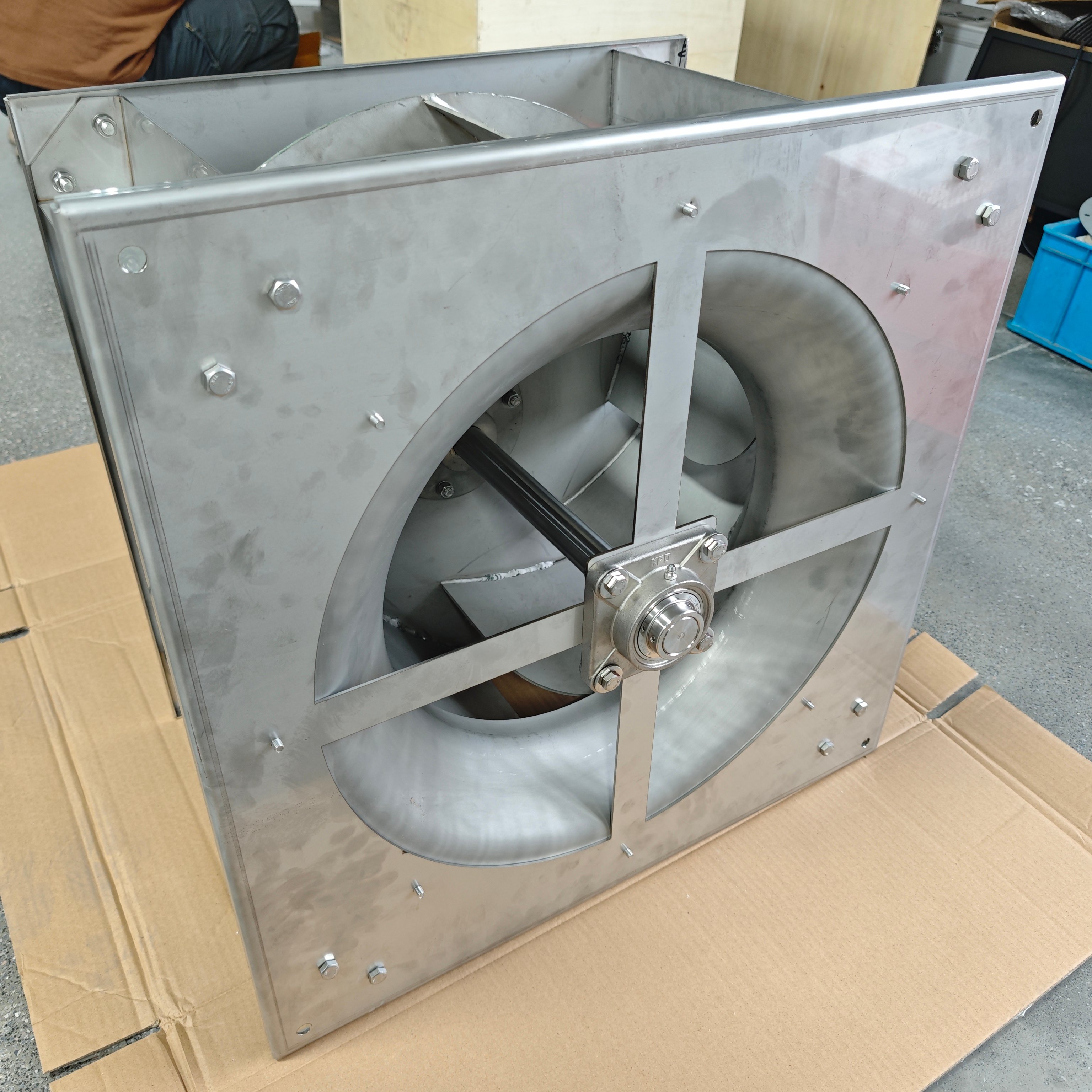
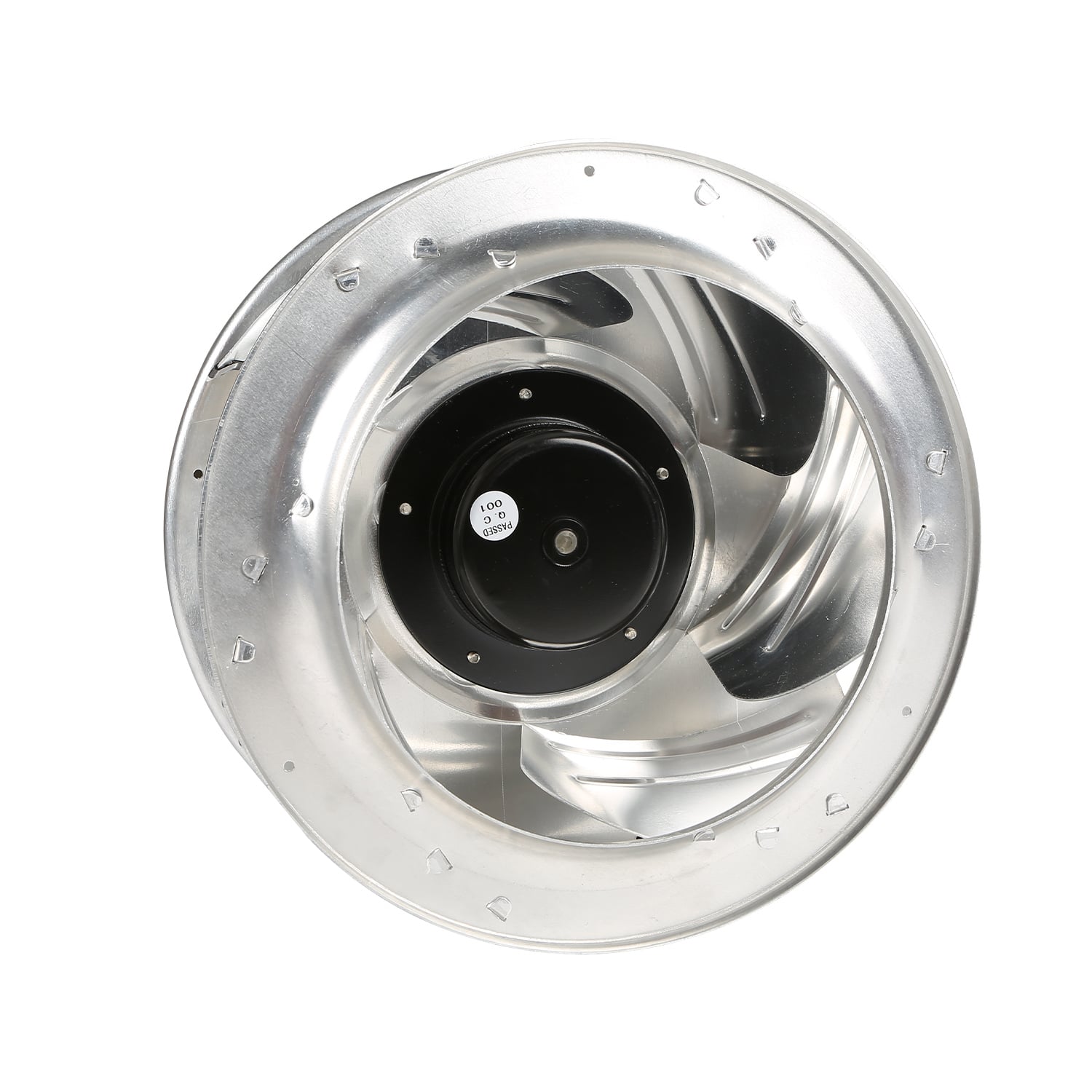
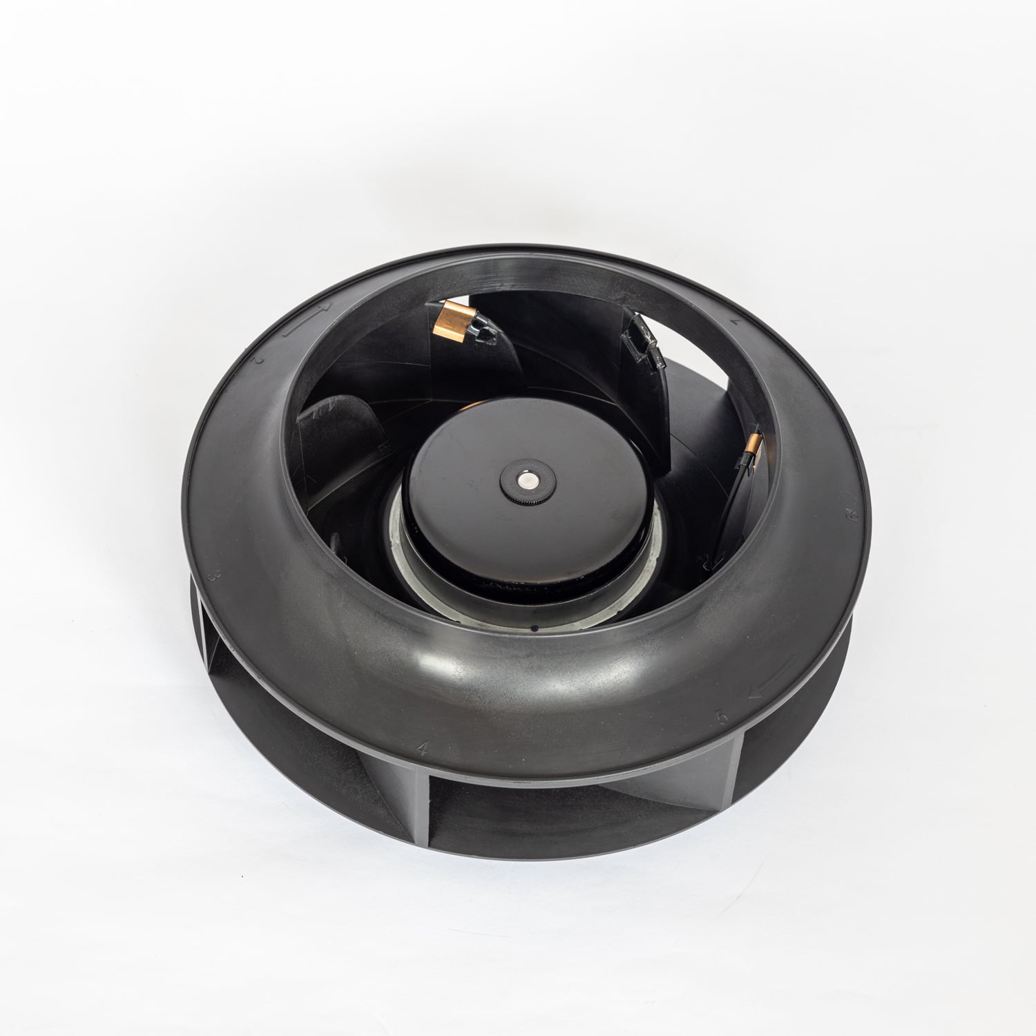
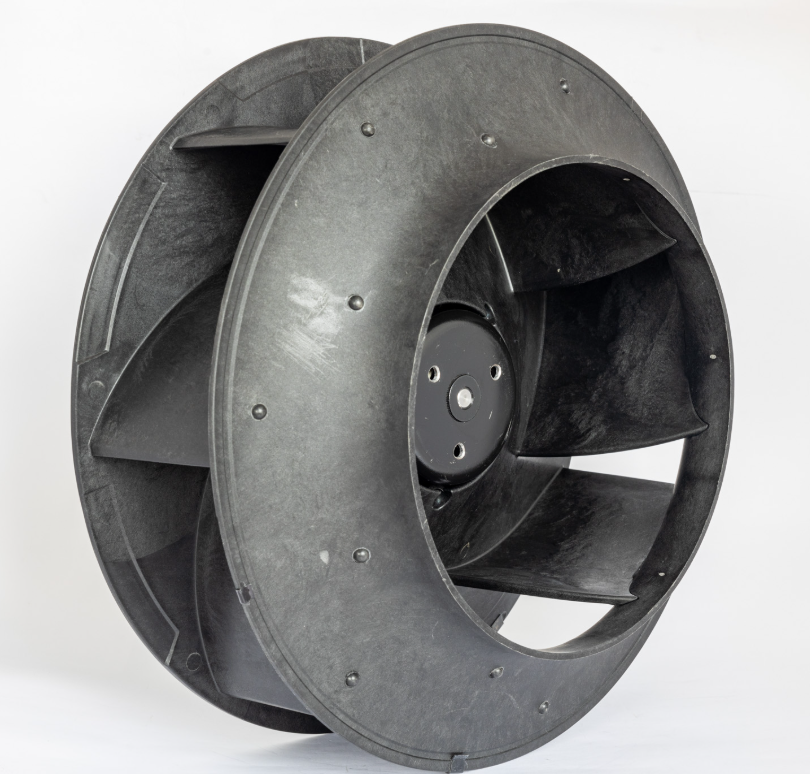
In petroleum and mining operations, the ventilation system is the single greatest line of defense for personnel safety underground. Methane accumulation, hydrogen sulfide drift, combustible dust suspension — these invisible hazards demand a level of engineering rigor from ventilation equipment that far exceeds conventional industrial requirements. At the center of every ventilation loop sits the centrifugal impeller, the sole rotating power element. Its material choice and structural design define the safety envelope of the entire system.
This article draws on field engineering experience to examine the SS316 austenitic stainless steel centrifugal impeller across three dimensions: material science, structural dynamics, and manufacturing process control — all within the context of explosion-proof, corrosion-resistant petroleum mine ventilation. For context on our full product range, see the FANOVA centrifugal fan catalog.
Key Takeaway (TL;DR)
SS316 is a molybdenum-bearing austenitic stainless steel with a PREN ≥ 24, significantly outperforming SS304 in chloride environments. When combined with an elastic block coupling to eliminate metal-to-metal spark risk and an independent bearing housing bracket to decouple vibration transmission, the three elements form the engineering optimum for mine-duty explosion-proof ventilation.

The airflow through a petroleum mine ventilation shaft is far from clean. Based on field sampling data, typical mine return air contains:
The simultaneous presence of these three corrosive agents demands that the impeller material simultaneously resist uniform corrosion, pitting corrosion, and chloride-induced stress corrosion cracking.
SS316 adds 2.0–3.0% molybdenum (Mo) to the SS304 base composition. This seemingly minor alloying adjustment produces an order-of-magnitude performance differential in chloride-bearing environments:
| Performance Metric | SS304 | SS316 | Test Standard |
|---|---|---|---|
| Pitting Resistance Equivalent (PREN) | ≥ 18 | ≥ 24 | PREN = %Cr + 3.3×%Mo + 16×%N |
| Critical Pitting Temperature (CPT) | ≈ 15°C | ≈ 25°C | ASTM G48 Method E (6% FeCl₃) |
| Cl⁻ SCC Threshold Concentration | ≈ 10 ppm (> 60°C) | ≈ 50 ppm (> 60°C) | NACE TM0177 |
| Uniform Corrosion Rate (5% H₂SO₄, 25°C) | > 1.0 mm/yr | < 0.3 mm/yr | ASTM G31 Immersion Test |
For mine return air operating conditions — temperature 25–45°C, RH 70–95%, Cl⁻ concentration 20–80 ppm — the CPT of SS304 sits squarely on the upper boundary of the operating window, whereas SS316 retains a margin of approximately 10°C. This is the core engineering judgment that drives the SS316 specification.
The impeller's blades are joined to the front and rear shrouds via continuous fillet welds. SS316 welding demands strict heat input control (recommended 0.8–1.5 kJ/mm) and interpass temperature management (≤ 150°C) to prevent chromium carbide precipitation in the heat-affected zone (HAZ), which would cause intergranular corrosion susceptibility. For impeller assemblies with material thickness ≤ 3 mm, TIG (GTAW) welding with ER316L filler wire is the standard process path — performed by a certified TIG welder, not automated. Post-weld pickling and passivation (HNO₃ + HF mixed acid bath) restores the passive Cr₂O₃ film integrity across all weld zones.
Explosion protection for mine ventilation equipment is governed by ATEX 2014/34/EU (EU) or GB 3836 (China) standards. Mechanical sparks represent a genuine ignition source: when a rotating impeller makes accidental contact with a stationary component, ferrous metal rubbing can generate incandescent particles exceeding 1,000°C.
SS316, as an austenitic stainless steel, is non-magnetic and non-hardenable. This means even under abnormal contact conditions, it does not produce the high-temperature friction sparks characteristic of carbon steel. But this is only the first layer of protection.
Engineering Principle: Explosion protection is never achieved by material selection alone. True safety comes from a multi-layer isolation design — material selection is layer one, structural isolation is layer two, and process control is layer three. Remove any layer and the safety case collapses.

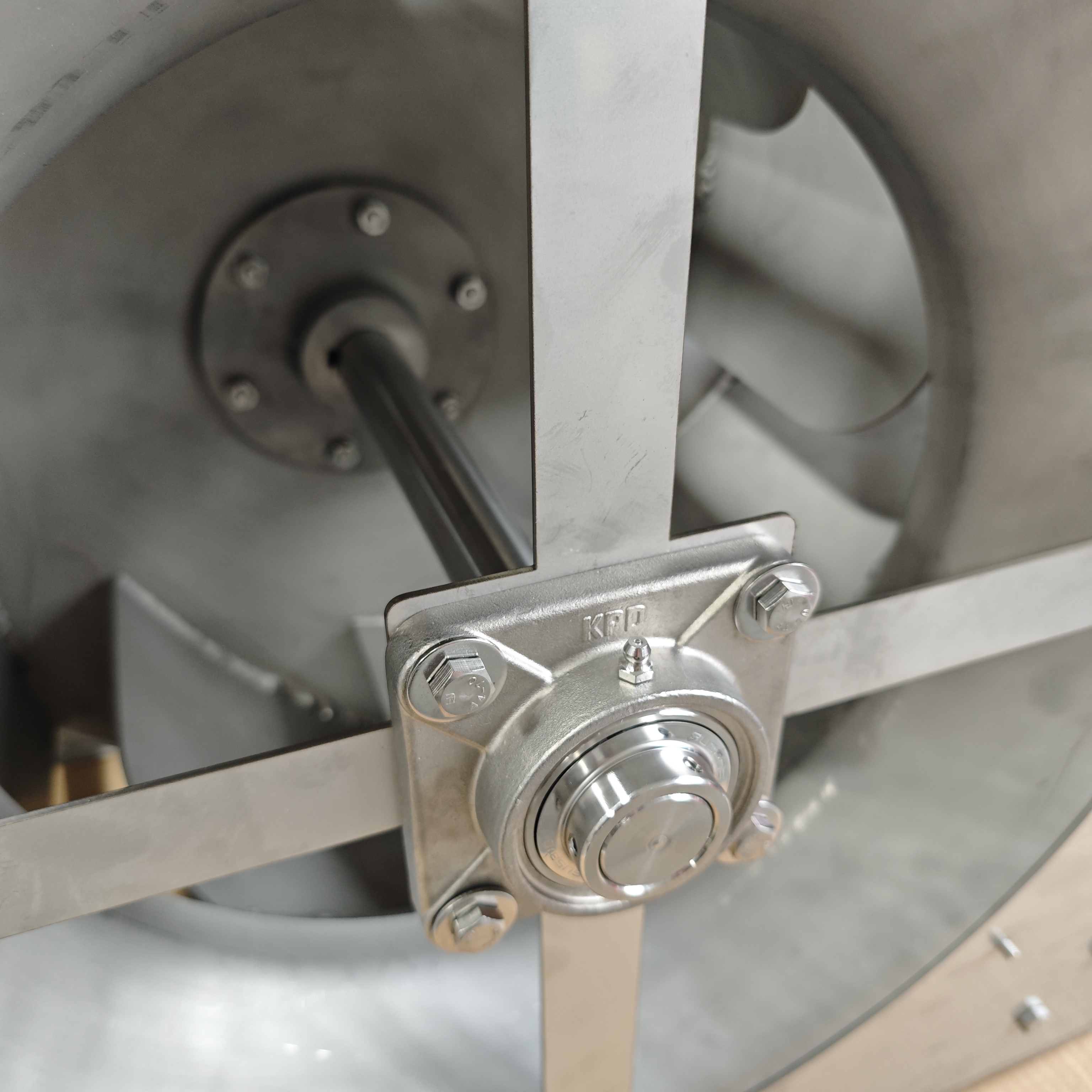
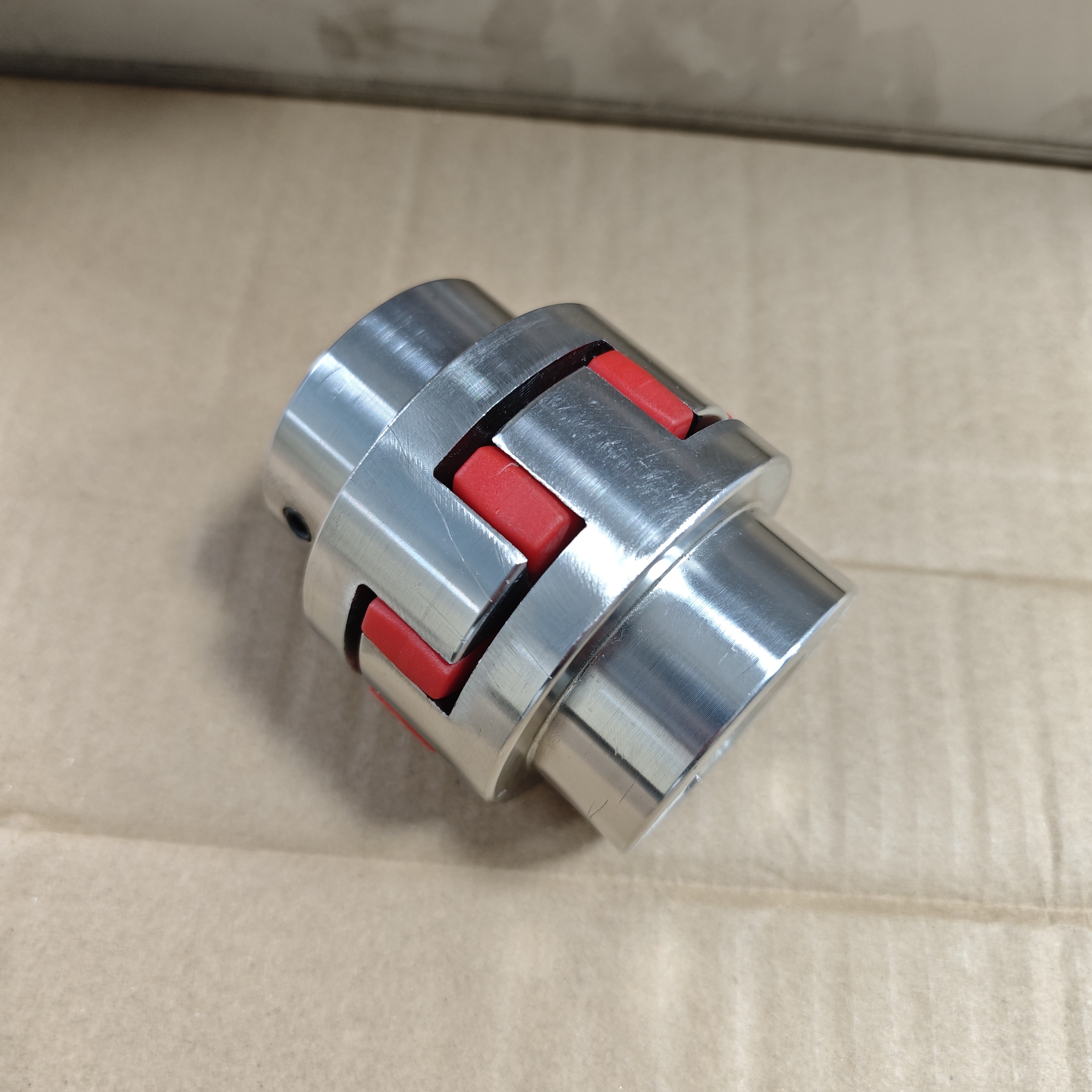
The elastic block coupling installed between the motor shaft and impeller shaft is the core safety feature of this custom design.
A polyurethane (PU) elastomer element is embedded between the two coupling flange halves to achieve the following:
The PU elastomer is specified at 92–95 Shore A hardness with a service temperature range of -30°C to +100°C, fully covering the operating temperature window of mine ventilation duty.

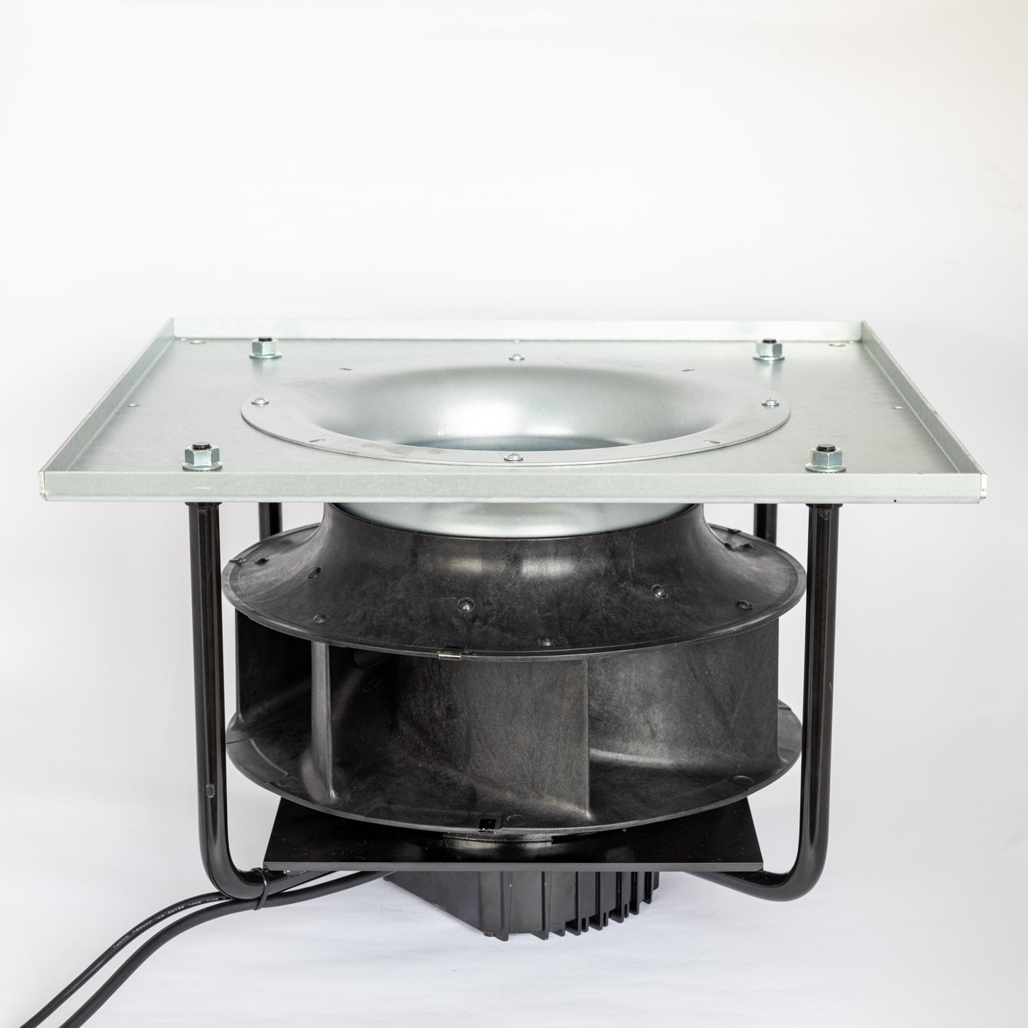
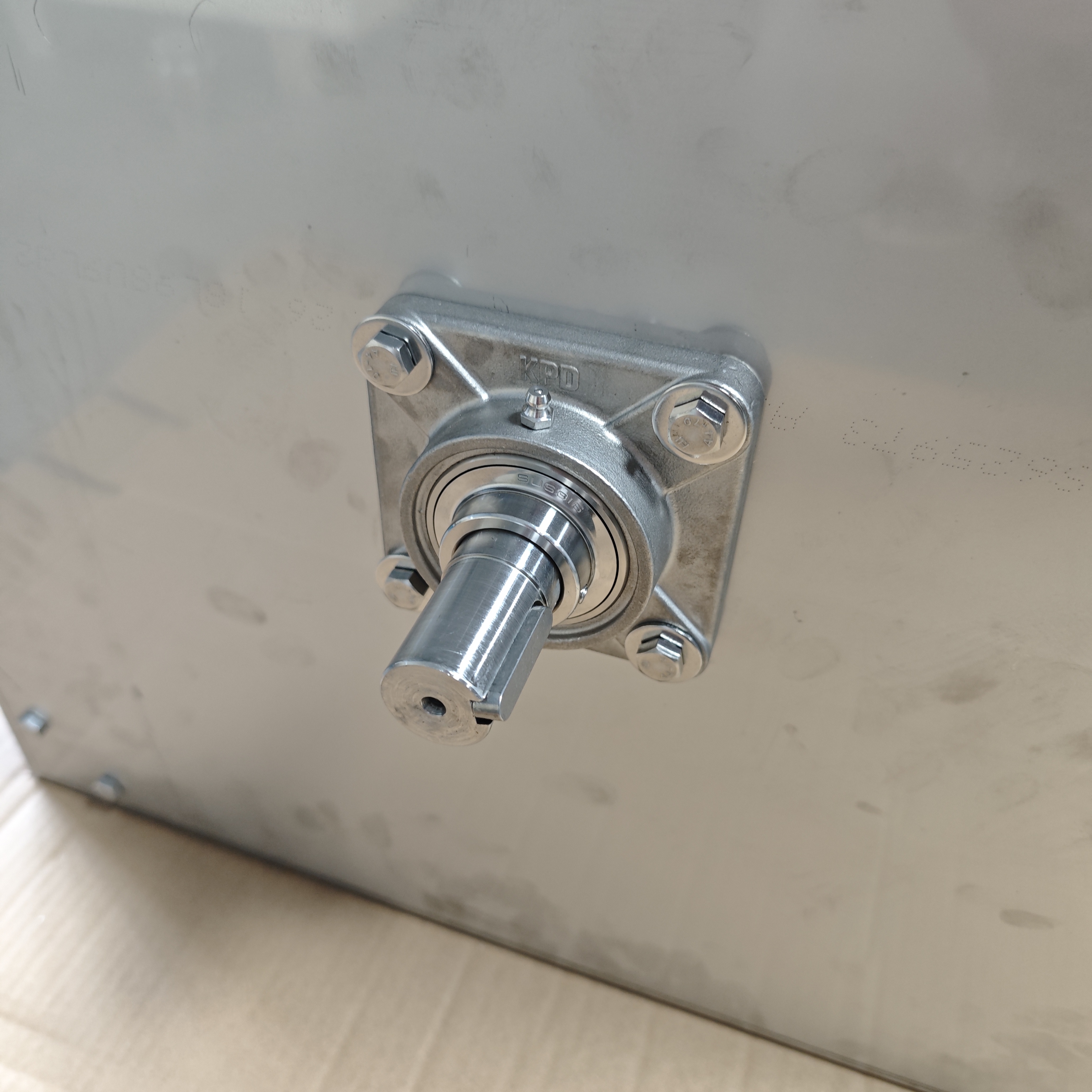
In conventional fan designs, the bearing housing is often bolted directly to the fan casing. This creates two failure pathways:
The independent bearing housing bracket design resolves both issues through the following structural features:
| Design Feature | Function | Safety Implication |
|---|---|---|
| Bearing housing separated from fan casing | Blocks casing-to-bearing vibration path | Actual bearing life approaches theoretical L₁₀ |
| Cast iron housing + SS316 base plate | Vibration damping + corrosion barrier | Cast iron damping coefficient (η ≈ 0.01) far exceeds steel (η ≈ 0.002) |
| Four-bolt flange with shim-adjustable positioning | Alignment accuracy ≤ 0.05 mm | Eliminates parasitic loads from misalignment |
| Thermal barrier gasket at mounting interface | Thermal conductivity < 0.5 W/m·K | Prevents heat soak into bearing under transient conditions |
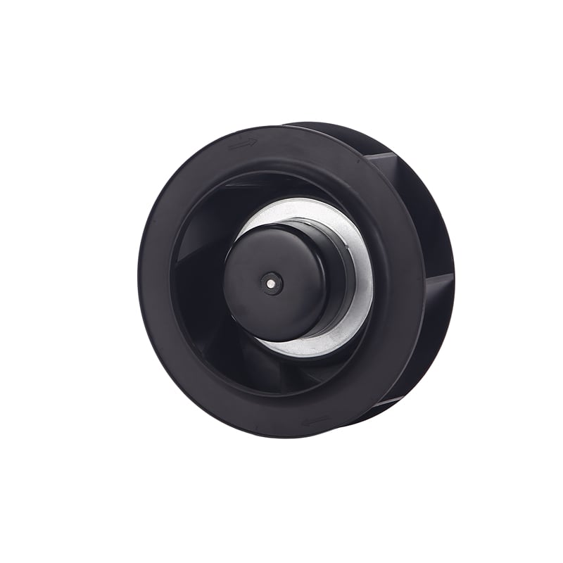
Centrifugal impellers are classified into forward-curved, radial, and backward-curved blade types. Mine ventilation adopts backward-curved blades whose power characteristic curve is self-limiting: when flow exceeds the design point, shaft power decreases rather than increases, providing intrinsic overload protection.
This means that even if the duct damper is inadvertently left fully open, the motor will not be driven into overload and overheat. In an explosion-hazard environment, any overheating of electrical equipment is unacceptable — the impeller's aerodynamic profile is itself a safety device.
The thermal expansion coefficient of SS316 (16.0 × 10⁻⁶ /K, 0–100°C) is approximately 40% higher than that of carbon steel. Welding distortion control is the single greatest fabrication challenge. The qualified process sequence is as follows:
All TIG welding is performed by a certified GTAW welder — manual TIG, not automated — to ensure full joint penetration and consistent bead profile across the complex three-dimensional blade-to-shroud intersections. This is a craft-level operation, not a production-line process. For a detailed look at our fabrication capabilities, see our manufacturing and quality assurance overview.
After welding, the impeller undergoes two-plane dynamic balancing to ISO 21940-11 Grade G2.5. For mine ventilation duty, the permissible residual unbalance is given by:
Uper = 9,550 × G × m / n
where G = 2.5 mm/s, m = impeller mass (kg), n = rated speed (rpm)
For a typical φ630 mm SS316 impeller (mass ≈ 28 kg, rated speed 2,900 rpm), the calculated permissible residual unbalance is approximately 230 g·mm. In production practice, this is controlled to ≤ 60% of the allowance (≤ 140 g·mm).

| Parameter | Frequency | Alarm Threshold |
|---|---|---|
| Bearing vibration velocity | Continuous (online monitoring) | > 4.5 mm/s RMS (ISO 10816-3) |
| Bearing temperature | Continuous | > 85°C (safe upper limit for standard grease) |
| Impeller surface inspection | Every 3 months | Pitting depth > 0.2 mm |
| Coupling elastomer inspection | Every 6 months | Cracks or permanent compression set ≥ 2 mm |
| Dynamic balance re-verification | Annually | Residual unbalance exceeding G2.5 tolerance |
Q1: Rust spots appearing on the impeller surface?
SS316 can still exhibit minor pitting in aggressive chloride environments. Verify that Cl⁻ concentration has not exceeded the design basis (> 200 ppm). If confirmed, upgrade the specification to SS316L (low-carbon variant, C < 0.03%) or duplex stainless steel 2205 (PREN ≥ 34).
Q2: Premature bearing failure (operating life < 8,000 h)?
Investigate coupling alignment condition and shaft system resonance. With the independent bearing housing design, bearing failure root cause is almost always upstream — inspect the elastomer element for degradation. Replace if necessary and re-align.
Q3: Gradual airflow decline?
Mine dust can accumulate in impeller flow passages, particularly under high humidity conditions, forming adherent deposits. Clean regularly (high-pressure water wash + compressed air dry). Never use a steel wire brush — scratching the passive film will accelerate pitting initiation.

| Parameter | Specification | Remarks |
|---|---|---|
| Impeller type | Centrifugal, backward-curved blades | Self-limiting power characteristic |
| Material | SS316 (UNS S31600, 06Cr17Ni12Mo2) | Upgradable to SS316L / 2205 duplex |
| Blade count | 6–8 | Optimized per specific speed |
| Welding process | TIG (GTAW), ER316L filler, manual certified welder | Post-weld pickling & passivation |
| Coupling type | Elastic block coupling (PU 92–95 ShA) | Electrical isolation + vibration decoupling |
| Bearing housing | Independent cast iron housing + SS316 base plate | Four-bolt flange, shim-adjustable |
| Dynamic balance grade | ISO G2.5 | Production control to 60% of tolerance |
| Service temperature range | -20°C to +80°C (standard) | High-temperature variant available to 200°C |
| Explosion protection standard | ATEX 2014/34/EU / GB 3836 | Full assembly certification with Ex-rated motor |
| Warranty | 12 months | Material and workmanship defects under rated conditions |
The application of SS316 stainless steel centrifugal impellers in petroleum mine ventilation is not a simple material substitution exercise. It is a systems engineering problem spanning corrosion science, structural dynamics, welding metallurgy, and explosion protection standards. An elastic block coupling eliminates the spark risk at the shaft interface. An independent bearing housing bracket decouples vibration transmission. Backward-curved blades provide intrinsic aerodynamic overload protection. These three design decisions form the engineering safety triad for mine ventilation duty.
Behind every parameter choice in this article is a failure case or validation dataset accumulated over more than a decade of field experience in petroleum and mining ventilation. For technical inquiries or to discuss a specific mine ventilation application, contact the FANOVA engineering team.