 EN

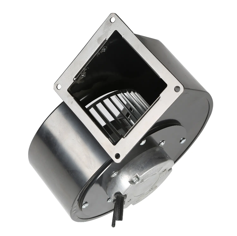
What an EC Blower Fan Really Is
An EC blower fan is a centrifugal air mover driven by an electronically commutated motor. The EC motor is a brushless permanent magnet design with drive electronics built into or mounted on the motor. The blower section, often a wheel inside a scroll housing, creates pressure and moves air through ducts or process equipment. The motor controls how fast that wheel turns.
The term can be confusing. Some suppliers use blower for any pressure building fan. Others mean a specific volute housing. In both cases, an EC blower fan pairs an impeller with a motor that follows a control signal instead of running at one fixed speed. Most systems rarely need full airflow all day.
Inside the Motor, Electronics, and Impeller
The rotor carries permanent magnets. Power transistors switch the stator windings. Hall sensors or back electromotive force tell the controller where the rotor is, and the controller chooses which winding receives current next. Electronic commutation replaces brushes and a mechanical commutator.
Integrated drives often add soft start, overcurrent limiting, locked rotor protection, and speed feedback. Common inputs include 0 to 10 V, PWM, frequency, and serial protocols such as Modbus or RS485. A tachometer output can confirm actual speed.
The impeller matters just as much. Centrifugal wheels pull air into the center and throw it outward. Forward curved wheels move high airflow at lower pressure. Backward curved wheels usually handle higher pressure with better efficiency. The scroll housing slows the air and converts velocity into static pressure. A mismatched motor and impeller may spin smoothly but miss the duty point.
Why Partial Load Behavior Changes the Game
Fan laws are simple and harsh. Airflow changes roughly with speed, pressure with the square of speed, and power with the cube of speed. That cube relationship explains why speed control often matters more than one peak efficiency number. A blower at 80 percent speed can use far less power than a full speed unit with a damper creating resistance.
AC induction motors with VFDs are a proven option. The difference is packaging and controllability. An EC motor often holds efficiency better at partial load because the permanent magnet rotor does not need magnetizing current. Electronics add cost and need protection from heat, moisture, and voltage spikes.
| Feature | AC induction blower | EC blower fan |
|---|---|---|
| Motor type | Squirrel cage induction | Brushless permanent magnet with integrated drive |
| Speed control | Damper, multi tap, or external VFD | 0 to 10 V, PWM, or serial command |
| Partial load behavior | Efficiency often drops away from rated point | Efficiency tends to hold up across a wider range |
| Starting current | Can be several times rated current | Usually closer to rated current with soft ramp |
| Controls integration | Often needs separate VFD and wiring | Drive and controls often integrated |
| Noise profile | Airflow and bearing noise dominate | Lower airflow noise at reduced speed, possible PWM tone |
| Maintenance focus | Bearings and capacitors | Bearings and drive electronics |
Those are typical patterns, not guarantees. Wheel design, housing, system resistance, and installation all change the result. AMCA Standard 210 and ISO 5801 define air performance tests because blower claims need a controlled setup.
A Real World Retrofit That Made the Problem Visible
During a retrofit at a chemical plant in southern China, the project team found a scrubber exhaust line held at negative pressure by an AC centrifugal blower running at full speed. A manual damper on the discharge side was partly closed to trim airflow. The damper worked, but it turned useful pressure into noise and heat. The motor drew high current even when the process was idle.
The team replaced the fixed speed unit with an EC volute fan and tied speed to a differential pressure sensor across the scrubber. When process load dropped, the fan slowed down. When hood dampers opened, it ramped up. Corrosive vapor required a coated impeller and a protected motor enclosure. A low speed resonance near 35 percent command was skipped in the controls.
Over a normal week, fan power fell by a double digit percentage, and operator complaints about constant roar dropped. The lesson was not that EC technology fixes every airflow problem. Matching speed to demand exposed how much energy the damper had been hiding.
Limits, Tradeoffs, and Misread Spec Sheets
EC blowers are not immune to bad applications. Electronics dislike high ambient temperatures, condensing humidity, salt spray, and voltage spikes. In a foundry or high temperature oven, a standard EC package may need remote mounting or extra thermal protection. Explosive atmospheres require special design.
Another mistake is comparing wattage at only one point. A blower must deliver airflow against the system resistance curve. If an EC fan cannot reach the required static pressure at the required flow, lower power means little. Wheel diameter, blade shape, inlet geometry, and scroll cutwater all shape the curve. A smaller EC unit can lose to a larger AC unit when the larger impeller matches the duct system better.
Noise expectations also need a reality check. Low speed usually reduces airflow noise, but PWM switching can create a tone that stands out. Mounting, isolation, and duct layout still matter. An EC blower bolted to a thin panel can transmit vibration like any rotating machine.
How to Match an EC Blower to the Duty Cycle
Start with the real duty cycle, not one design point. Record required airflow, static pressure, inlet temperature, and how much time the system spends at low, medium, and high demand. Then compare the fan curve with the system curve. Their intersection is the operating point. If that point sits far from the fan's efficient area, a different wheel or housing helps more than a different motor.
Next, decide how speed will be commanded. A pressure sensor, temperature sensor, flow station, or manual potentiometer can drive an EC blower. Control gain affects stability. Too much gain causes hunting. Too little makes the fan sluggish. A soft ramp and minimum speed limit often prevent short cycling.
Plan service access too. Bearings still wear, and the drive board needs reasonable airflow and a clean environment. Filters, screens, and duct transitions should be checked at commissioning.
Fanova has focused on EC fan manufacturing since 2003, with in house development and production of EC centrifugal fans, axial fans, and volute fans. The company supports industrial, commercial, and household airflow projects through motor and fan design, plastic material exploration, manufacturing process control, and supply chain coordination. For buyers comparing EC blower options, production depth can matter as much as a catalog number.