 EN

System Pressure Is a Match Between Fan Curve and Duct Curve
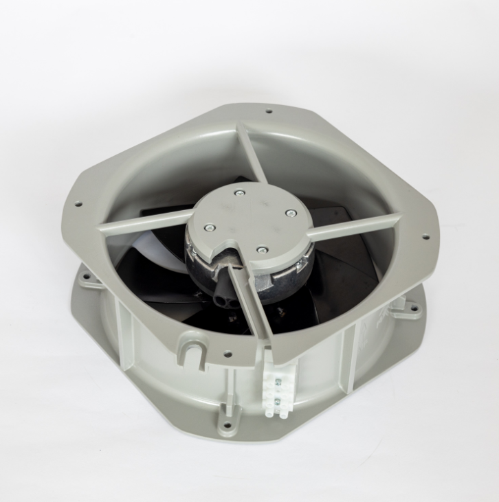
A backward curved ec fan is often chosen when a project needs stable pressure across a duct system that keeps changing. The key idea is that system pressure is not a fixed number printed on a fan nameplate. It is the intersection of the fan curve and the system resistance curve. Add a longer duct run, a loaded filter bank, or a tighter louver, and the system curve steepens. A fixed speed fan then slides left on its curve, losing airflow. An EC backward curved centrifugal fan can move that intersection by changing speed, but only within its motor and impeller limits. Understanding this match prevents the common mistake of buying a fan with a high shutoff pressure and assuming the duct will behave.
What Backward Curved Blades Do to Static Pressure
Backward curved blades leave the impeller at a lower absolute velocity than forward curved blades, so less energy stays locked in high velocity air. The volute and outlet diffuser then convert what remains into static pressure with less turbulence. That is why a backward curved impeller tends to hold a healthier static pressure share at the duty point, especially in medium to high pressure air handlers. Forward curved wheels can move a lot of air in a small package, but their outlet velocity is high and the pressure conversion is more dependent on a clean outlet path. Radial blades tolerate dirty streams better but usually pay in noise and efficiency. None of this is magic. Blade angle, impeller width, inlet cone fit, and cut-off clearance all shift the curve.
EC Speed Control Keeps Setpoint as Filters Load
A backward curved EC fan gains another lever from the motor. Electronically commutated motors allow smooth speed changes without a separate VFD panel, and the control can take a pressure or airflow signal directly. In a filter loading scenario, a differential pressure transmitter watches the drop across the filter bank. As dust builds, the controller raises speed to hold the setpoint. The fan curve shifts upward until the motor reaches its speed or current limit. This is useful in cleanrooms, paint booths, and lab exhaust, where a small pressure drift can affect containment or product quality. It is less useful when the system has a huge fixed resistance and the fan is already near maximum speed at clean filter conditions.
A Comparison That Helps Retrofit Decisions
| Evaluation point | Forward curved AC belt fan | Backward curved AC belt fan | Backward curved EC fan |
|---|---|---|---|
| Pressure style | High airflow in compact size, more dynamic head | Strong static pressure share, steadier curve | Same impeller advantage plus speed control |
| Part load control | Damper or inlet vane, fixed speed | Damper, VFD, or sheave change | Integrated electronic speed command |
| Filter loading response | Flow falls as resistance rises | Flow falls unless speed is adjusted | Closed loop pressure or airflow correction |
| Typical turndown | Limited without separate VFD | Limited without separate VFD | Often 3:1 or wider, depending on motor |
| Maintenance focus | Belts, bearings, alignment | Belts, bearings, alignment | Bearings, electronics environment, sensor |
| Acoustic tradeoff | High outlet velocity, tonal noise | Lower outlet velocity, blade pass tone | Similar aerodynamics, motor whine possible |
A Paint Shop Retrofit That Needed More Than a New Impeller
A retrofit at an automotive paint shop in eastern China showed why system pressure deserves field measurement, not just catalog selection. The original forward curved belt driven fan served a booth exhaust duct that had been extended twice. Operators complained about weak capture at the far end, so the first proposal was a larger motor and a faster sheave. That would have raised airflow, but it also would have pushed duct velocity and noise higher. The project team measured static pressure at the hood, across the filters, and at the fan inlet. The readings showed a sharp loss at a tight elbow right before the fan. The replacement used a backward curved EC fan with a pressure sensor at the booth plenum. During commissioning, the speed rose as filters loaded, but the real fix was a turning vane in the elbow. Without that vane, the EC fan would have run faster and louder while chasing a pressure loss caused by bad inlet conditions. The case is a useful reminder that fan curves assume decent inlet and outlet conditions, as described in AMCA 210 and ASHRAE 51 test setups.
Limits, Standards, and a Smarter Specification Path
Backward curved EC fans have boundaries. Dusty or sticky airstreams can coat the impeller and shift balance. High ambient temperature around the motor electronics may force derating. Harmonic and EMC reviews matter when many EC drives share a panel. Performance should be compared using AMCA 210 or ISO 5801 data, with sound power reported by octave band, not a single dB number. IEC 60034-30-1 helps classify motor efficiency, but it does not replace fan system testing. A smart specification lists airflow range, static pressure range, turndown, sensor type, acceptable sound at the occupied space, and the control signal from the BAS. Fanova, based in Suzhou, supports that work with in house design, tooling, and production for EC centrifugal fans, axial fans, and volute fans, which helps keep prototype iterations, quality checks, and supply planning coordinated for industrial, commercial, and household air systems.
Table of Contents
- System Pressure Is a Match Between Fan Curve and Duct Curve
- What Backward Curved Blades Do to Static Pressure
- EC Speed Control Keeps Setpoint as Filters Load
- A Comparison That Helps Retrofit Decisions
- A Paint Shop Retrofit That Needed More Than a New Impeller
- Limits, Standards, and a Smarter Specification Path