 EN

Airflow Starts With the System Curve, Not the Motor Label
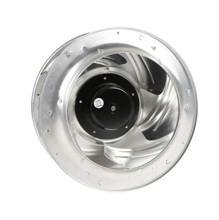
A high efficiency ec fan can deliver more airflow than an older fixed speed unit, but the gain does not come from a magic motor label. Airflow is set by the intersection of the fan curve and the system resistance curve. Duct length, filter loading, elbow geometry, and outlet conditions all shape that resistance. A fan with a steep curve may hold pressure better as filters load, while a fan with a flatter curve may move more air at low resistance. The EC motor adds a useful lever because speed can be adjusted electronically, but the impeller, housing, and inlet conditions still decide how much air the package can move before noise, vibration, or motor limits step in. Projects that start with a measured system curve usually get a more honest airflow result than projects that start with a catalog headline.
Where a High Efficiency EC Fan Finds Extra Airflow
Three mechanisms tend to matter in real projects. First, an efficient EC motor reduces electrical and magnetic losses, so more input power reaches the shaft for a given operating point. That does not mean unlimited airflow, but it can help a fan hold duty without pushing the electrical supply as hard. Second, electronic speed control allows the impeller to run faster when the system needs more air, provided the motor, bearings, and impeller are rated for that speed. Third, integrated control can respond to a pressure or airflow sensor, so the fan corrects for filter loading instead of drifting below setpoint. A fourth factor sits outside the fan: reducing avoidable system resistance, such as a sharp inlet elbow or a collapsed flexible duct, often frees more airflow than a motor change alone.
A Practical Comparison of Airflow Levers
| Airflow lever | AC belt driven fan | High efficiency EC fan | Field note |
|---|---|---|---|
| Speed adjustment | Sheave change or separate VFD | Integrated electronic speed command | Faster commissioning, fewer coordination points |
| Filter loading response | Airflow falls unless manually adjusted | Closed loop pressure or airflow correction | Sensor location matters more than the control algorithm |
| Motor losses at duty point | Higher losses in many older designs | Lower motor losses, but fan efficiency still dominates | Compare fan system data, not motor data alone |
| Inlet and outlet losses | Same duct penalties apply | Same duct penalties apply | Fixing a tight elbow can outperform a fan upgrade |
| Noise at higher airflow | Belt and bearing noise plus aerodynamic noise | Aerodynamic noise rises with speed | Review octave band sound power, not a single dB value |
| Turndown range | Limited without added controls | Often wider, depending on motor and impeller | Confirm limits with the manufacturer |
A Cleanroom Retrofit Where Duct Resistance Set the Ceiling
A retrofit at an electronics cleanroom in eastern China offered a grounded example. The existing belt driven centrifugal fan served an air handling unit with a prefilter and a final filter bank. Operators reported low airflow at the far end of the cleanroom, especially after filter loading. The first idea was a larger motor and a faster sheave. Measurements told a different story. Static pressure readings showed a sharp loss at a tight inlet elbow and a high pressure drop across a partially loaded prefilter. The replacement used a high efficiency EC fan with a pressure sensor at the supply plenum, plus a turning vane in the elbow and a more frequent prefilter change schedule. During commissioning, the EC fan raised speed as the final filter loaded, and the airflow at the far diffusers reached the design range without the noise penalty that a simple speed increase would have caused. The lesson was not that EC fans solve every airflow problem. It was that motor efficiency and speed control work best when the duct path is not fighting the fan.
The Limits That Keep Airflow Claims Honest
EC fans have boundaries that deserve respect. Motor speed has a mechanical limit set by bearings, impeller stress, and critical speed. Pushing speed beyond the rated range may raise airflow on paper but shorten bearing life or increase vibration. High ambient temperature around the electronics can force derating, which reduces available shaft power. Harmonic and electromagnetic compatibility reviews matter when many EC drives share a distribution board. Fan performance should be compared using AMCA 210 or ISO 5801 test data, with sound power reported by octave band. IEC 60034-30-1 helps classify motor efficiency, but it does not describe fan system efficiency. A realistic airflow plan also checks filter pressure drop, duct leakage, and control sensor placement. Otherwise a new fan may chase a setpoint that the duct system cannot support.
Specifying Airflow Without Overpromising
A useful specification lists the airflow range, static pressure range, required turndown, sensor type, acceptable sound at the occupied space, and the control signal available from the building management system. Ask for fan curves that include the selected impeller and housing, not just motor data. For variable filter or variable occupancy projects, request a part load control narrative that explains how airflow is maintained and what happens when a sensor fails. Fanova, a Suzhou based EC fan manufacturer, supports that process with in house design, tooling, and production for EC centrifugal fans, axial fans, and volute fans, which helps keep prototype iterations, quality checks, and supply planning aligned for industrial, commercial, and household air systems.