 EN

HVAC Efficiency Is a System Problem, Not a Motor Badge
Air handling units rarely fail on efficiency because one component is bad. They fail because the fan, filters, coils, dampers, and duct path are commissioned as separate items. An ec cooling fan for hvac can help, but only when the air path is measured and the control sequence is clear. Fan energy is one part of the picture. Coil pressure drop, filter loading, duct leakage, and sensor placement often decide whether a retrofit delivers savings or just a new nameplate. A fan with electronic speed control cannot fix a duct system that leaks 15 percent of its air or a pressure sensor installed in a dead zone. The practical starting point is a short measurement walk: static pressure at the fan inlet and outlet, pressure drop across each filter bank, and a check of damper positions at design and part load.
What an EC Cooling Fan Actually Changes in an Air Handler
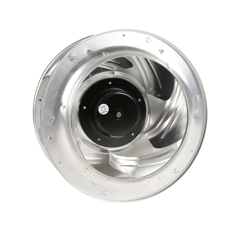
The useful change is not just a different motor. An EC cooling fan uses a brushless motor with an integrated inverter, so speed can be commanded smoothly without a separate VFD panel. That gives the control sequence a direct lever on airflow. In a variable air volume box or a filter loaded air handler, a pressure signal can raise or lower speed to hold setpoint. The motor also avoids belt losses and sheave alignment issues, which removes a few maintenance points. The aerodynamic package still matters. Impeller shape, inlet cone fit, and housing clearance decide how much static pressure the fan can produce at a given speed. A good EC package pairs a stable fan curve with a control range that matches the actual part load profile. A fan that is already near maximum speed at clean filter conditions has little room to correct as filters load.
A Side-by-Side View of Control and Maintenance Tradeoffs
| Decision area | Traditional AC belt drive | EC cooling fan for HVAC | Field implication |
|---|---|---|---|
| Speed control | Sheave change or separate VFD | Integrated electronic command | Fewer panel and wiring coordination points |
| Part load response | Damper or inlet vane throttling | Direct speed turndown, often 3:1 or wider | Better match to variable occupancy |
| Filter loading | Airflow drifts unless manually adjusted | Closed loop pressure or airflow correction | Sensor location drives results |
| Maintenance points | Belts, pulleys, bearings, tension checks | Bearings, electronics environment, sensors | Different skill set for service teams |
| Acoustic behavior | Belt and bearing noise plus aerodynamics | Lower mechanical noise, motor tone possible | Review octave band sound power |
| Retrofit footprint | Belt guard and alignment space | Compact motor and impeller package | Useful in tight mechanical rooms |
A Hospital Air Handler Retrofit That Revealed Sensor Placement
A retrofit at a hospital in eastern China offered a grounded example. The existing belt driven supply fan served an operating suite air handler with a prefilter and a final filter bank. Staff reported pressure swings after filter changes, and the original fix was to run the fan at a fixed high speed. Measurements showed a different problem. The differential pressure sensor was installed downstream of a turning vane, in a spot with swirling flow, so the reading jumped whenever the damper moved. The project team replaced the fan package with an EC cooling fan and relocated the sensor to a straight duct section with a flow straightener. During commissioning, the fan speed moved in small steps as the final filter loaded, and the room pressure band stayed tighter than the old fixed speed routine. The team also sealed a leaking access door on the return plenum. Without that door fix, the fan would have chased a setpoint while pulling unfiltered air. The case is a reminder that ASHRAE Standard 90.1 fan power limits and AMCA 210 or ASHRAE 51 test data describe equipment, not the installed system.
The Boundaries That Keep HVAC Efficiency Claims Honest
EC cooling fans have limits. Electronics need a clean, dry, and thermally managed enclosure. High ambient temperature near a rooftop unit may force derating. Harmonic and electromagnetic compatibility reviews matter when many drives share a panel. Motor speed has a mechanical ceiling set by bearings, impeller stress, and critical speed. A pressure sensor can fail or drift, so the control sequence needs a safe fallback. Duct leakage and damper leakage can erase part load savings. Fan curves should be compared on a common basis, with sound power reported by octave band, not a single dB number. IEC 60034-30-1 helps classify motor efficiency, but it does not replace fan system testing. Honest savings estimates include filter change intervals, actual occupancy schedules, and the cost of electrical upgrades.
Specifying EC Cooling Fans Without Overpromising
A useful specification lists airflow range, static pressure range, required turndown, sensor type, acceptable sound at the occupied space, and the control signal from the building management system. Ask for fan curves that include the selected impeller and housing, not just motor data. For projects with variable filters or variable occupancy, request a part load control narrative that explains how setpoint is maintained and what happens when a sensor fails. Fanova, a Suzhou based EC fan manufacturer, supports that work with in house design, tooling, and production for EC centrifugal fans, axial fans, and volute fans, which helps keep prototype iterations, quality checks, and supply planning aligned for HVAC, purification, and other air systems.
Table of Contents
- HVAC Efficiency Is a System Problem, Not a Motor Badge
- What an EC Cooling Fan Actually Changes in an Air Handler
- A Side-by-Side View of Control and Maintenance Tradeoffs
- A Hospital Air Handler Retrofit That Revealed Sensor Placement
- The Boundaries That Keep HVAC Efficiency Claims Honest
- Specifying EC Cooling Fans Without Overpromising