EN
EN

DANNIS LUO · FANOVA APPLICATION ENGINEERING · September 2026
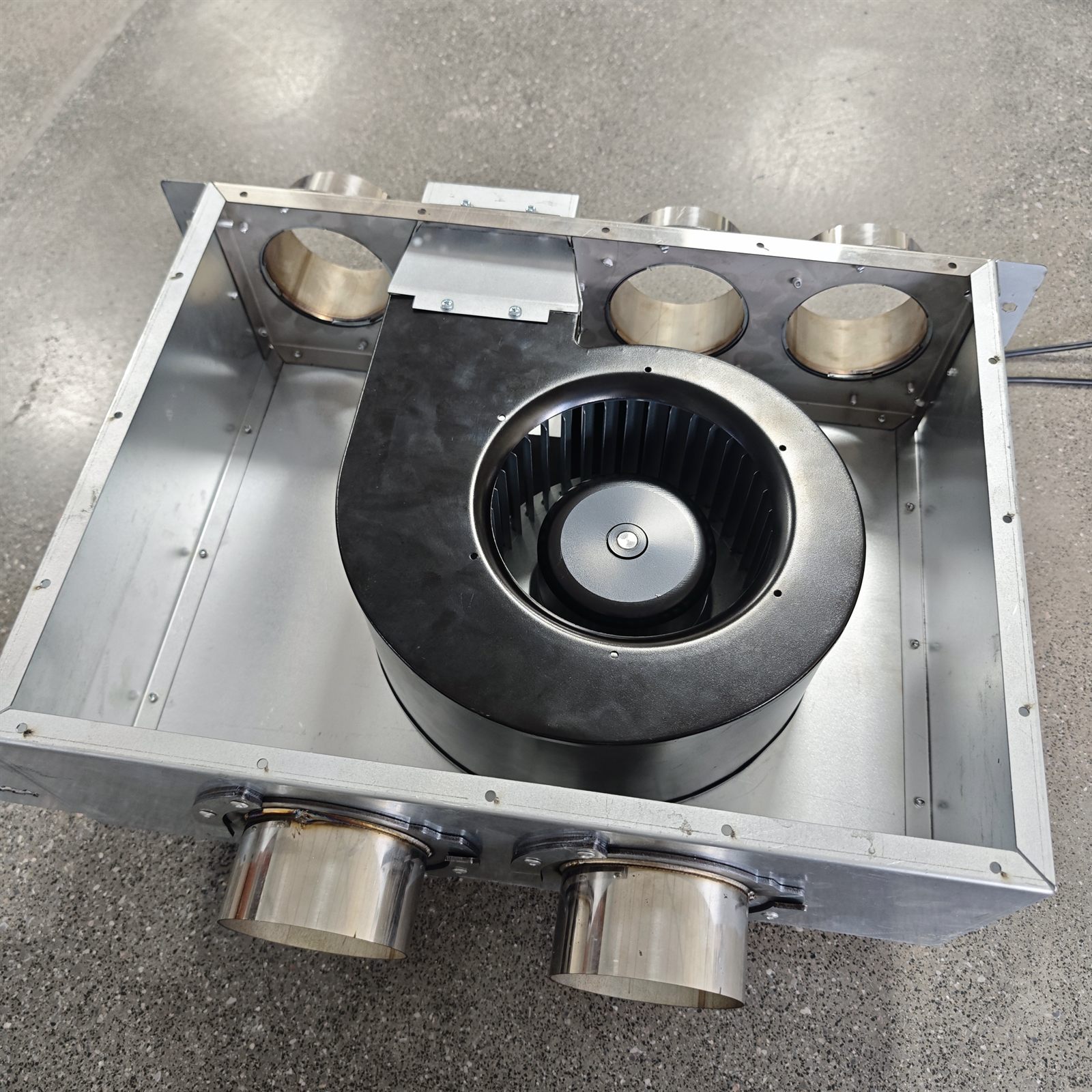
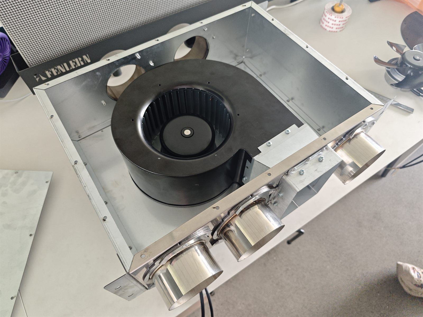
A commercial tanning equipment maker in Southeast Asia sent us the drawing package for an LED module fan assembly. The box measures 530 x 453 x 218 mm and weighs 7.74 kg fully built. Inside sits one blower. It feeds five twist-lock couplers and one square louvered port, which carry air to the bed's LED modules.
The customer's question was narrow: which fan family holds airflow across six parallel outlets from a single source? For LED module cooling the airflow figures on the datasheets were not the deciding factor. The static pressure was.
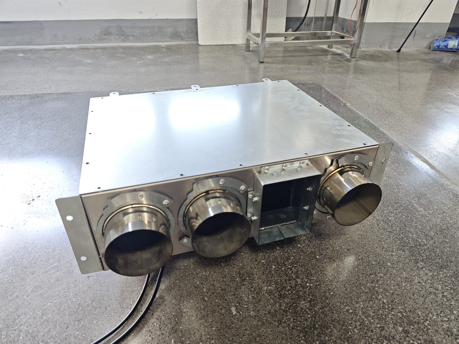
An LED module cooling box is a manifold, not an open air path. Air leaves one blower and must be divided across five twist-lock couplers plus a louvered port. Every coupler, every duct run and every louver blade adds resistance, in series and in parallel.
Two constraints made the specification tighter than a general ventilation duty. The box is small, so the blower has to deliver that pressure from a compact impeller. And the assembly sits inside equipment used by a person, so sound pressure level becomes part of the product experience.
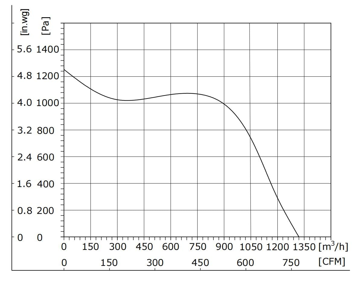
Every fan curve has two endpoints: free-air flow at zero restriction, and maximum static pressure with the outlet fully blocked. A real installation lives between them, at the intersection of the fan curve and the system curve.
The industry rule of thumb is straightforward. Axial fans work economically up to roughly 100 Pa of system resistance. Centrifugal blowers take over above 300 Pa, and where total system pressure falls between 100 and 200 Pa the decision usually favours a centrifugal design.
Because system pressure drop rises with the square of flow rate, the system curve steepens quickly. This is what punishes a low-pressure fan in a branched box: the axial unit may post a comparable free-air number, but it reaches that number only near zero resistance, and it retreats down its curve as soon as the couplers and louver are connected.
Now apply that to an LED module cooling box with six outlets.
| Model | Type | Max. airflow | Max. static pressure | Power | Noise |
|---|---|---|---|---|---|
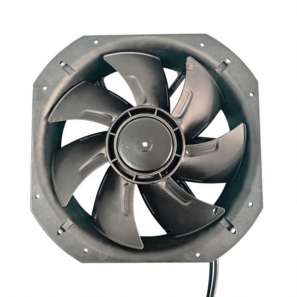
| FG3G200-2AGL-70 | Axial, 200 mm | 1,205 m3/h | 250 Pa | 45 W | 62 dB(A) |
| FG3G250-2AGL-90 | Axial, 250 mm | 1,740 m3/h | 226 Pa | 80 W | 61 dB(A) |
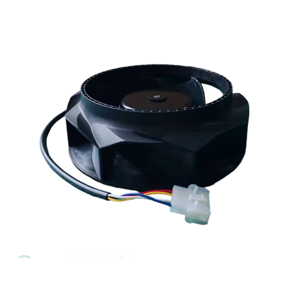
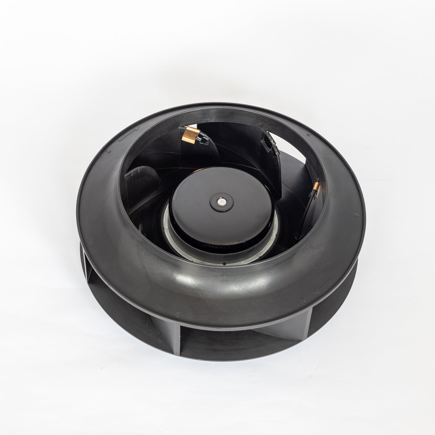
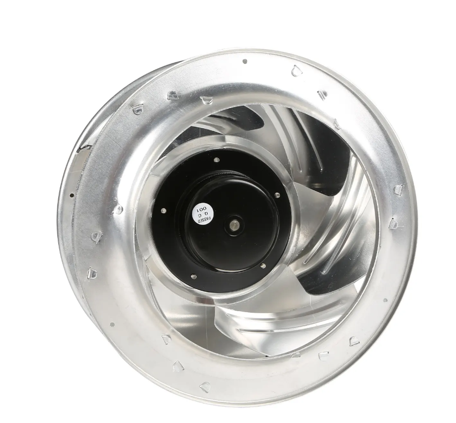
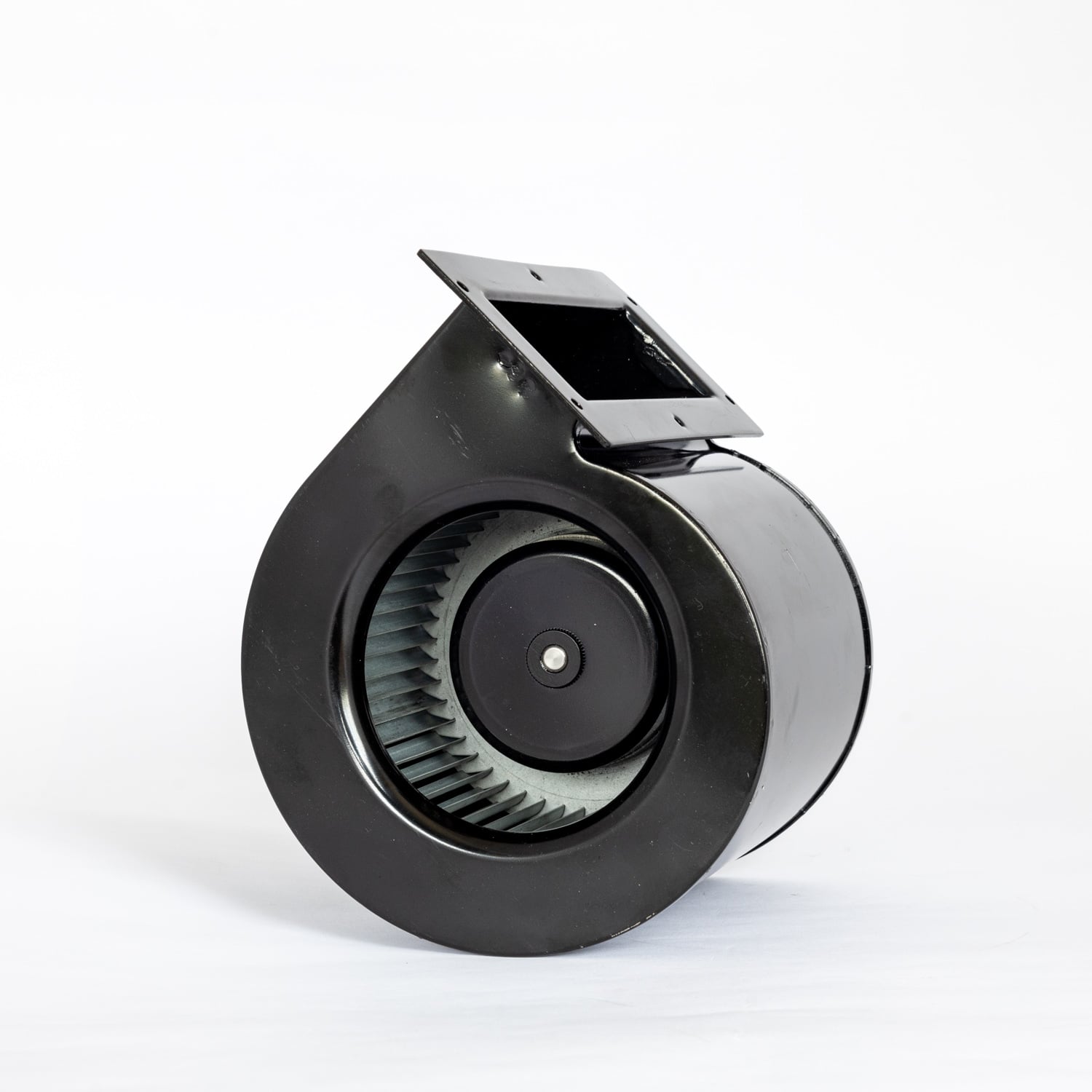
| FB3G250-2APS-90 | Backward-curved centrifugal, 250 mm | 1,590 m3/h | 762 Pa | 220 W | 77.1 dB(A) |
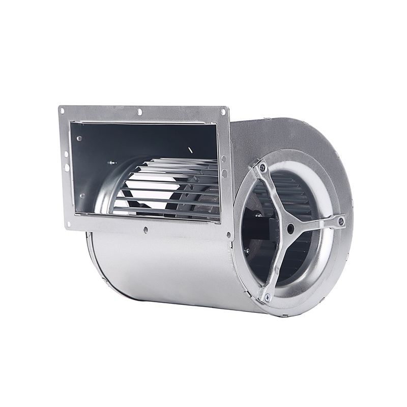
| FS3G180-2AGL-20 | Single inlet centrifugal, 180 mm | 1,320 m3/h | 1,265 Pa | 495 W | 76 dB(A) |
That is roughly five times the static pressure of a 200 mm axial fan, from a smaller impeller - and more than twelve times the 100 Pa edge of an axial fan's economic range.
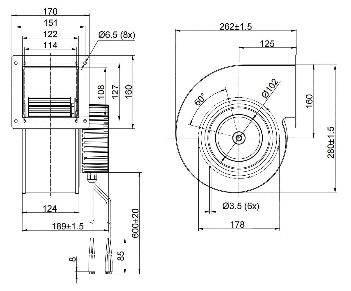
For this LED module cooling assembly FANOVA specified a single FS3G180-2AGL-20 - an EC single inlet centrifugal blower with a scroll housing and a 180 mm impeller. The radial discharge of a scroll housing is what produces the pressure head; the single inlet keeps the assembly compact enough for the 530 x 453 x 218 mm box.
| Parameter | Value |
|---|---|
| Model | FS3G180-2AGL-20 |
| Type | EC single inlet centrifugal blower, scroll housing |
| Nominal voltage | 230 VAC, single phase, 50/60 Hz (range 184-270 VAC) |
| Current draw | 2.2 A +/-10% |
| Speed | 2,460 rpm +/-5% |
| Power consumption | 495 W +/-10% |
| Max. air flow | 776.8 CFM / 1,320 m3/h |
| Max. static pressure | 5.06 in.wg / 1,265 Pa |
| Sound pressure level | 76 dB(A) +/-5 |
| Insulation class | Class B |
| Degree of protection | IP54 |
| Control input | 0-10 VDC or PWM |
| Signal output | FG tachometer, 3 pulses per revolution |
| Serial interface | RS485 MODBUS (RSA / RSB) |
| Impeller | 180 mm diameter, 38 blades, cold-rolled steel plate |
| Rotor diameter | 102 mm |
| Electronics housing | Die-cast aluminium |
| Motor | EC external rotor, ball bearings, S1 duty |
| Operating temperature | -25 to +60 degC ambient |
| Life expectancy | 50,000 hours (L10) at 40 degC |
| Weight | 6.5 kg |
| Approvals | CE, RoHS, ISO 9001, ErP 2015 |
A tanning bed is not a rooftop air handling unit. The blower sits in the same enclosure as the user. Sound pressure level stops being a background specification and becomes part of the product experience.
76 dB(A) is the price of 1,265 Pa. If your outlet count or duct length allows a lower pressure, the FS3G180-2AGL-90 does the same job at 70 dB(A) and 200 W instead of 495 W. We specified the higher-pressure version because the six-outlet layout required it, and because speed control recovers most of the difference in normal operation.
This is where an EC blower separates itself from a fixed-speed AC alternative. The 0-10 VDC or PWM input lets the controller set speed continuously. A thermistor on the LED module reads junction temperature, so fan speed rises only when the modules are hot and the bed runs at part speed during idle periods.
Holding 495 W at full speed for 3,650 hours a year consumes 1,807 kWh. Because fan power falls roughly with the cube of speed, running at part speed for most of that time cuts the figure substantially.
The same 180 mm impeller is available at other operating points if you are developing an LED module cooling range rather than a single model:
Three questions decide whether you need a centrifugal blower or can stay with an axial fan.
First, count the outlets and add up the duct length. Anything branched, anything over a few metres, anything with a louver or a filter, pushes you toward high static pressure.
Second, work from the system curve, not the free-air number. Estimate the resistance of every element, add ten to twenty percent reserve, then find where your blower curve crosses that value - this step decides most LED module cooling specifications.
Third, decide whether the load varies. If it does, an EC blower with a 0-10 VDC input repays the price difference in running cost, and the FG signal adds fault detection.
The specified FS3G180-2AGL-20 covers this LED module cooling layout from a single impeller: 1,320 m3/h and 1,265 Pa from a 180 mm wheel, inside a box measuring 530 x 453 x 218 mm. Speed control lets the maker trim airflow to LED junction temperature instead of running the blower flat out, and the FG tachometer output supports fault detection at the product level.